@Blitz
Yes, it is.
I would not suggest you using that 5V/2A rail for anything that may affect sound quality, especially everything after isolator.
Regards,
Ian
that was my understanding, the 5V/2A is for dirty stuff like digital front ends...
Yes, it is.
I would not suggest you using that 5V/2A rail for anything that may affect sound quality, especially everything after isolator.
Regards,
Ian
Yes, that's correct.
LifePO4 doesn't have 1.3V rail, so it has to be regulated from 3.3V battery rail. All other sections use 3.3V rails. So, I removed all LDOs to keep the quality of battery power.
If you can, the best way is to power each 3.3V load with independent battery rails. Please let me know how much in difference from powering them all with one battery rail.
Regards,
Ian
Well, that is plan Ian! But to do that, first you need to ship the LifePO4 power supplies
")
Thanks for explanation above!
My Fifo is safe to be fed with 3.3V rather than 5V without problem. On board LDO will be bypassed automatically if the drop voltage is less than 0.3V.
For clock board, is also OK, but to reach best possible sound quality, I would suggest remove or bypass on board LDOs if you feed it with 3.3V battery rails.
Regards,
Ian
Is this also the case with McFIFO; e.g. feeding 3.3V would automatically bypass LDO or do I need to manually change something?
Ian,
Looking at the markings on the dimensions PDF, a couple are trimmed, but I think they should read 176mm and 168mm.
Also, I notice that the max DC out is limited to 13.3V. Is this correct? For one of my applications I will need the full 16.5V output of the five batteries each side. Is this possible?
Anthony
Is this also the case with McFIFO; e.g. feeding 3.3V would automatically bypass LDO or do I need to manually change something?
In McFIFO, you can simply remove the onboard LDO, which just use a little effort to break the connection between the small LDO board and the motherboard, and then directly connect the input and output of the LDO with the wire, let the 3.3V from the battery directly input to McFIFO.
Ian,
Looking at the markings on the dimensions PDF, a couple are trimmed, but I think they should read 176mm and 168mm.
Also, I notice that the max DC out is limited to 13.3V. Is this correct? For one of my applications I will need the full 16.5V output of the five batteries each side. Is this possible?
Anthony
Hi Anthony,
Each battery rail is independent and isolated, so you can just simply put them in serial to reach 16.5V. In this case, each power supply has two 16.5V rails. If you need more rails, you can run more LifePo4 power supplies together by using a bridge cable.
Regards,
Ian
In McFIFO, you can simply remove the onboard LDO, which just use a little effort to break the connection between the small LDO board and the motherboard, and then directly connect the input and output of the LDO with the wire, let the 3.3V from the battery directly input to McFIFO.
For McDual XO you can do it so to reduce power supply internal resistance even more. But for McFifo, you don't need to.
Regards,
Ian
For McDual XO you can do it so to reduce power supply internal resistance even more. But for McFifo, you don't need to.
Regards,
Ian
My mistake, I think of McFIFO as McDual XO.
If I am not mistaken, McFIFO should not need to be powered by batteries, use a general linear power supply?
Last edited:
My mistake, I think of McFIFO as McDual XO.
If I am not mistaken, McFIFO should not need to be powered by batteries, use a general linear power supply?
Yes, you are right. It's not really necessary for anything before isolator to use battery power.
Ian
@acg
There are 3 ways to turn on/off the LifePO4 power supply.
1. Press and hold the knob encoder on the OLED panel.
2. Form a external control button which is connected to the on/off PIN on the PCB.
3. By the on/off signal (3,3V-12V DC level, input is isolated) from external master power supply or controller through the bridge cable socket. This feature makes it possible that more LifePO4 power supplies can be bridged together to have more voltage rails or higher voltage.
Regards,
Ian
@acg
There are 3 ways to turn on/off the LifePO4 power supply.
1. Press and hold the knob encoder on the OLED panel.
2. Form a external control button which is connected to the on/off PIN on the PCB.
3. By the on/off signal (3,3V-12V DC level, input is isolated) from external master power supply or controller through the bridge cable socket. This feature makes it possible that more LifePO4 power supplies can be bridged together to have more voltage rails or higher voltage.
Regards,
Ian
Why not buy an RF module for an option? The RF module in this photo is only for $2. Taobao can bought a remote control module that supports Android phones.


Last edited:
Hi.
I would like to use LifePO4 battery supply for my TDA1541A DAC but the data sheet for TDA1541A says Max +/- 5,5V and - 16V with absolute max @ +/- 7V and -17V. LiFePO4 can supply +/- 6,6V and -16,5 V.
A little too close to the absolute max.
Has anyone tried this?
Would it degrade the direct battery power quality if i place a silicon diode in series with each of the three supply lines? That would lower the voltages to +/- 6V and -15,9V...
Ian LiFePO4 Power supply principle block diagram
Voltage rails:
1, Low noise linear regulated 5V 2A: for digital sections (before isolator is suggested);
2, Pure LifePO4 battery power 3.3V: for clock board;
3, Pure LifePO4 battery power 3.3V: for DAC;
4, Pure LifePO4 battery power 3.3V or 6.6V or 9.9V or 13.2V: for I/V stages or analog sections;
5, Pure LifePO4 battery power 3.3V or 6.6V or 9.9V or 13.2V: for I/V stages or analog sections;
All voltage rails are independent from each other.
All battery powered rails are isolated from DC input
Multiple LifePO4 boards can be bridged together for more power rails.
Normal laptop power adapter would be good option as DC input.
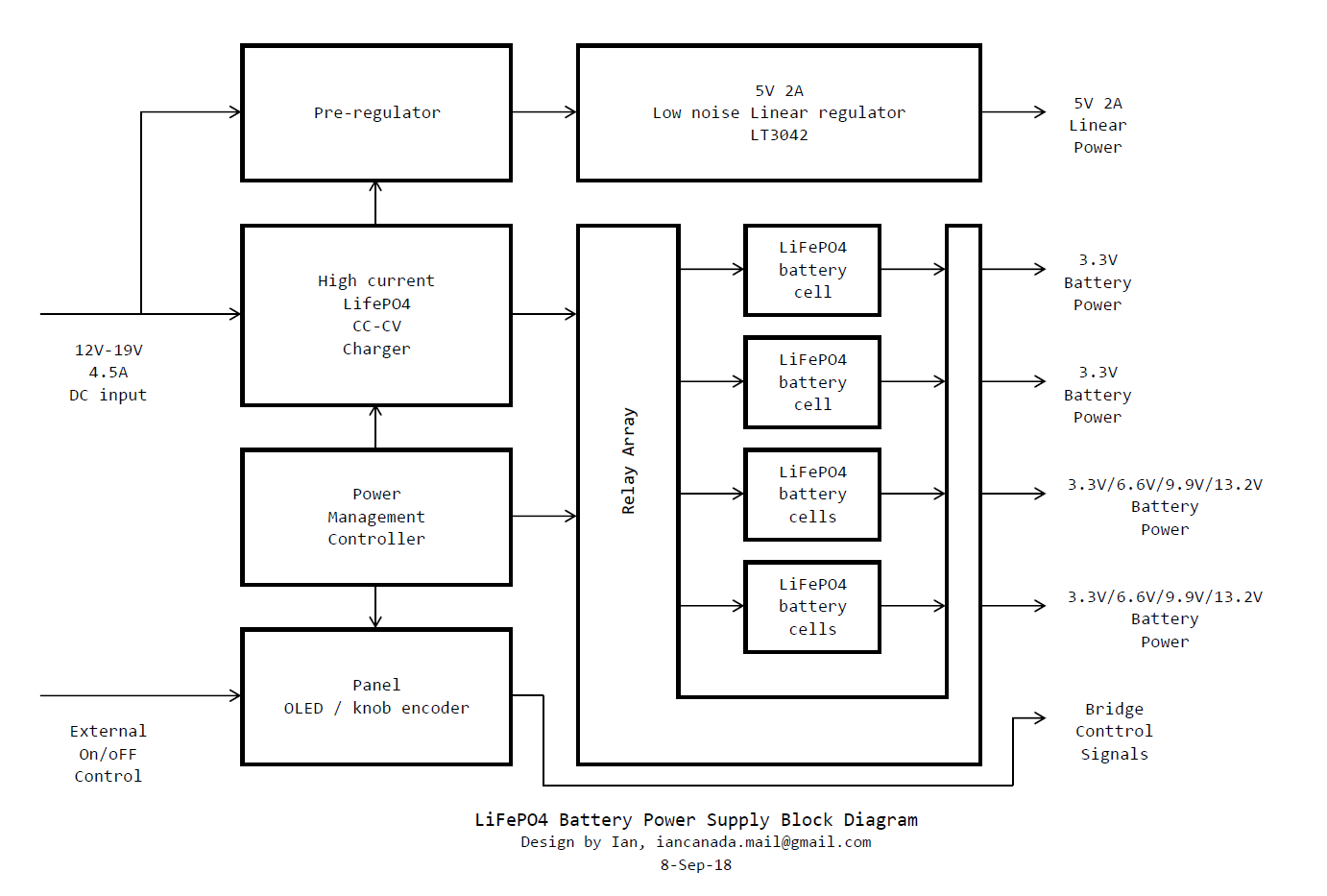
LifePO4PowerSupplyBlockDiagram by Ian, on Flickr
Ian
Let me see if I get it right for my battery order:
- Each board has four battery rails.
- So if each of them would have 3.3V, this means four batteries to buy...right ? Or did you configured the board so that you could use all the slots for batteries in any case, resulting in a higher capacity by paralleling batteries ?
If I want 26V: Possible with two battery rails in series (...for the CCS of my LTP-Tube stage) ?
Best Regards
Frank
- Home
- Amplifiers
- Power Supplies
- Develop ultra capacitor power supply and LiFePO4 battery power supply