So I got to do a little more work with this tonight.
I also made a new discovery - I wanted to check if it was something like I had the pot badly adjusted, and as I turned it one way looking at the scope I noticed that the frequency changed with pot rotation. Then just as I did that the noise stopped completely. This was repeatable across both polarities. However, when I connected different loads, I saw the noise return, and then I could adjust it out, change the load back and then it would be there again etc.
Unless I hear different from someone here I think my next move is to change out the power BJTs. These ones are working pulls from an amp, but I have brand new ones from mouser as well. The BD139/140 are brand new from mouser. After that I'm at a loss.
- So first off, the issue is exactly the same across two separate builds. So its not something isolated to just one build.
- The frequency of the noise is a relatively clean sine wave at mid 30s mHz
- Amplitude of the noise/oscillation etc is variable I've seen 10mV to 30mV rms
- In both cases, the size of the load affects whether the noise is there or not
I also made a new discovery - I wanted to check if it was something like I had the pot badly adjusted, and as I turned it one way looking at the scope I noticed that the frequency changed with pot rotation. Then just as I did that the noise stopped completely. This was repeatable across both polarities. However, when I connected different loads, I saw the noise return, and then I could adjust it out, change the load back and then it would be there again etc.
Unless I hear different from someone here I think my next move is to change out the power BJTs. These ones are working pulls from an amp, but I have brand new ones from mouser as well. The BD139/140 are brand new from mouser. After that I'm at a loss.
So I got to do a little more work with this tonight.
- So first off, the issue is exactly the same across two separate builds. So its not something isolated to just one build.
- The frequency of the noise is a relatively clean sine wave at mid 30s mHz
- Amplitude of the noise/oscillation etc is variable I've seen 10mV to 30mV rms
- In both cases, the size of the load affects whether the noise is there or not
I also made a new discovery - I wanted to check if it was something like I had the pot badly adjusted, and as I turned it one way looking at the scope I noticed that the frequency changed with pot rotation. Then just as I did that the noise stopped completely. This was repeatable across both polarities. However, when I connected different loads, I saw the noise return, and then I could adjust it out, change the load back and then it would be there again etc.
Unless I hear different from someone here I think my next move is to change out the power BJTs. These ones are working pulls from an amp, but I have brand new ones from mouser as well. The BD139/140 are brand new from mouser. After that I'm at a loss.
You could try ferrite cores on the base of the transistors.
I was wondering about a stopper resistor on the bases, but no-one else seems to have needed that.
Yeah, so this turned out to be oscillation of the BD139/BD140 transistors. I added a grid stopper of 240r on both and the problems disappeared. No detectable ripple even when pulling 3.5A, and no observable difference at lighter loads. There is some noise/hash of a few mV or so, but that is there anyway on bench when not connected to anything. The whole PSU sags a bit naturally under the 3.5A load, I'm getting about +/-28Vdc from a 2x25VAC 300VA transformer at that load, and about 31-32Vdc unloaded.
I'm still not sure as to why it oscillated at different loads, one thing is that the BD139/140 are mounted on their full length legs to facilitate a little bend in the legs to let the heatsink stick out a bit away from the caps. They weren't on extensions or anything, still on their own legs, but higher up than you would normally mount them. Once the stoppers were in, no oscillation observed at 1.5A or 3.5A. Power BJTs barely even get warm so I think it will be fine to mount them to the floor of the chassis, maybe even with a heat spreader or something.
i would be suspecting fake parts, but these are fresh from mouser a couple of weeks ago.

Just a further thought. I don't think I ever would have caught this without a scope. I consider myself an entry novice at using a scope, but it has proved very useful here for sure. The oscillation would never have shown up as AC because of the high frequency.
Thanks Fran. I wonder if the oscillation is actually a problem? Audible? Or would it overheat the BDs..?! Just thinking out loud.!
Yes, I am also wondering. 🤔Thanks Fran. I wonder if the oscillation is actually a problem? Audible? Or would it overheat the BDs..?! Just thinking out loud.!
Just finished populating my boards a few weeks ago and they are just waiting for the amp boards to be finished. Should I mod my boards before they start duty?
If you have access to a scope, its worth sticking the scope on the outputs under a few loads, not necessarily as heavy as the ones I did. I saw sine wave oscillation at 30-something mHz at anywhere from 10-40mV or so. Nothing only noise/hash kind of stuff at a few mV once the stoppers were on. This was on the boards without the rectifiers as shown above.
I previously built one using another board that @jimk04 kindly sent me, its a very similar board but it has onboard rectifiers - so I went back and scoped that last night, and there was no sign of any oscillation there. So this might be something that is weird in my setup, or on those boards, or my parts choices, my voltages. Who knows!!
As to what harm it would do - I don't know. But you'll never "see" this by checking for AC at the output with a DMM because the frequency will make the meter think its DC, and you won't notice 30-40mV of DC in the middle of the output. My Bd139/140 never got hot, so you wouldn't tell from that either. However, I can't think its a good thing to feed even a small signal like that through the output devices on an amp. I don't think adding the resistor has a down side - and I used 240r, but I'd imagine anything from 200-400r should work OK. In the world of valves anything from 100r to 1k would be grand, but transistors might be fussier. I just picked 240r on a whim, there was no scientific basis to that! The usual advice is to get that stopper resistor as physically close as possible to the base pin, so mounting it on the pin would be best.
Nice write up Fran.
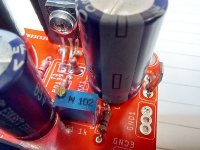
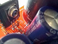
Guys I've just taken out my 3255 amp that I run with a big old unregulated psu. Using this Capmx after a decent cap bank. I noticed just now this resistor is obviously having a hard time.
Any thoughts?!


Guys I've just taken out my 3255 amp that I run with a big old unregulated psu. Using this Capmx after a decent cap bank. I noticed just now this resistor is obviously having a hard time.
Any thoughts?!
jimk04, you will have to be more specific - which board and schematic is that? There are several different boards on this thread and from the looks of it yours are not the same as the ones Fran measured.
My guess is that resistor should be a 2 or 3W resistor. Difficult to say from the photo.
Also - is it not beter practice to have a cap bank after the Cap Mx?
My guess is that resistor should be a 2 or 3W resistor. Difficult to say from the photo.
Also - is it not beter practice to have a cap bank after the Cap Mx?
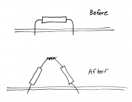
An easy upgrade:
In place of a 3.0 ohm, 0.5 watt resistor . . . . connect two 1.5 ohm, 1 watt resistors in series, mounted vertically. Resistor 1 goes into PCB hole 1, Resistor 2 goes into PCB hole 2, they are pushed together and their midpoint leads are twisted, soldered, and trimmed. Now you've got a 3.0 ohm, 2 watt resistor. Viewed from the side, the two resistors form a very pretty isosceles triangle.
In place of a 3.0 ohm, 0.5 watt resistor . . . . connect two 1.5 ohm, 1 watt resistors in series, mounted vertically. Resistor 1 goes into PCB hole 1, Resistor 2 goes into PCB hole 2, they are pushed together and their midpoint leads are twisted, soldered, and trimmed. Now you've got a 3.0 ohm, 2 watt resistor. Viewed from the side, the two resistors form a very pretty isosceles triangle.
3 ohm....in a position that calls for 2k? Sorry to doubt but I am inexperienced enough to have to ask!
In place of an X ohm, Y watt resistor . . . . connect two (X/2) ohm, (2*Y) watt resistors in series, mounted vertically. Resistor 1 goes into PCB hole 1, Resistor 2 goes into PCB hole 2, they are pushed together and their midpoint leads are twisted, soldered, and trimmed. Now you've got an X ohm, (4*Y) watt resistor. Viewed from the side, the two resistors form a very pretty isosceles triangle. You've quadrupled the power handling capability!!!
Substitute whatever values of X and Y you like. Perhaps X=2K, Y=0.5W . Perhaps X=3, Y=1 . The calculations work the same way for both cases.
_
Substitute whatever values of X and Y you like. Perhaps X=2K, Y=0.5W . Perhaps X=3, Y=1 . The calculations work the same way for both cases.
_
Attachments
@jimk04
I suspect your wattage rating on that resistor is a bit low. That's the drain resistor (if I'm right) that collapses down the voltage in the big reservoir caps if the load is dropped (well its pulling some current all the time). I would replace with a higher wattage resistor mounted off the board by a few mm, or else follow as @Mark Johnson suggests. If your PSU is running at eg 30V then that resistor is continuously dissipating 1/2W, if your voltage is 40V then its 0.8W.
I think I would use a 3k resistor there instead (or even 4k7). At 30V, 3k would see 1/4W, so a 2W would be very safe. 4k7 would only see 0.16W, so a 1W would do fine. The other thing to think about is that you would probably be better having the capacitor bank after the cap-mx, although I'm guessing you have it set up that way because the normal PSU has the rectifiers on board.
Thanks guys yes that all makes sense. I didn't realise it was a bleeder. And its a 50v rail too !
I have some 2 or 3w that I can use vertically.
And I keep seeing the comments about Capmx before any other cap bank so I'll amend that too!
I have some 2 or 3w that I can use vertically.
And I keep seeing the comments about Capmx before any other cap bank so I'll amend that too!
Last edited:
yeah, 50V across 2k is 1.25W, so probably pushing it alright.
If you change it around the other way let us know how the sound is after.... I know when I added the bank of caps after the cap-mx in a class ab amp you could hear the difference in bass and dynamics/impact. You wouldn't be taking them back out for sure.
If you change it around the other way let us know how the sound is after.... I know when I added the bank of caps after the cap-mx in a class ab amp you could hear the difference in bass and dynamics/impact. You wouldn't be taking them back out for sure.
Hey people,
First, many thanks @ Juma, XRK971, Prasi and everyone who helped making these things real!
I'm driving three LM3886 per box with an unregulated PSU (18-0-18V) and about 50000µF/ rail (for all 3 Chipamps). I am really happy with these loudspeakers and, as a newbie, I cannot even imagine I could improve anything 😉. But, you know ...
In the ChipAmp-forum, the user "Kaltecs" (who developed very nice composite amps with the LM1875 & the TDA7293) wrote very positive about using Cap Multipliers with his Amps.
As the PSU in my speakers is still under construction anyways, I'd like to give a Cap Multiplier a try. So, as I just ordered different PCB's in China, I ordered some PCB's for the shown CapMu also >

The PCB's are now on their way from China, and I'd like to ask if you people maybe got some advice what to look at when building & using these things.
First a few questions:
I took the smaller PCB with two MOSFETs, because it will be installed in the PSU-compartment of the loudspeaker, where there is not much room. What is your advice, does each amp need it's own CapM, or one CapM per box?
I am not sure if I can afford 47000µF caps. Will 22000, maybe 2x 22000µF be ok?
What should I do with the already existing caps? Maybe three smaller ( it's 4700µF caps, maybe 10 (5 per rail) for each Amp) packs after the CapM, or how could I use them?
How much voltage drop will I have? Sooner or later I got to buy better toroids (300VA should be, now I got 160VA) and maybe I can order a few Volts more when I order at "shop toroidy" in Poland.
What else should I keep in mind?
best regards
J.
First, many thanks @ Juma, XRK971, Prasi and everyone who helped making these things real!
I'm driving three LM3886 per box with an unregulated PSU (18-0-18V) and about 50000µF/ rail (for all 3 Chipamps). I am really happy with these loudspeakers and, as a newbie, I cannot even imagine I could improve anything 😉. But, you know ...
In the ChipAmp-forum, the user "Kaltecs" (who developed very nice composite amps with the LM1875 & the TDA7293) wrote very positive about using Cap Multipliers with his Amps.
As the PSU in my speakers is still under construction anyways, I'd like to give a Cap Multiplier a try. So, as I just ordered different PCB's in China, I ordered some PCB's for the shown CapMu also >
The PCB's are now on their way from China, and I'd like to ask if you people maybe got some advice what to look at when building & using these things.
First a few questions:
I took the smaller PCB with two MOSFETs, because it will be installed in the PSU-compartment of the loudspeaker, where there is not much room. What is your advice, does each amp need it's own CapM, or one CapM per box?
I am not sure if I can afford 47000µF caps. Will 22000, maybe 2x 22000µF be ok?
What should I do with the already existing caps? Maybe three smaller ( it's 4700µF caps, maybe 10 (5 per rail) for each Amp) packs after the CapM, or how could I use them?
How much voltage drop will I have? Sooner or later I got to buy better toroids (300VA should be, now I got 160VA) and maybe I can order a few Volts more when I order at "shop toroidy" in Poland.
What else should I keep in mind?
best regards
J.
- Home
- Amplifiers
- Power Supplies
- Juma's Easy-Peasy Capacitance Multiplier