This is a bit off topic , but some of you have graciously shown completed amps.
To point out , setting up a star ground node , for the AG ( Audio Ground) , inside an Amp is quite important in order to minimize noise .
Have a look at the way Nelson Pass has set up the star ground inside his F5 .
On the top right , notice a green ground wire comes off the shield of the RCA , to a node on the Amp board .
A green ground wire comes off the cap board , to that same node.
No doubt the ground from the speaker binding post goes to this node
as well as the Audio Ground from the Amp itself.
So the Audio Grounds of the RCA , cap board, Amp and Speaker Posts are all referenced to the same " 0 " Vdc .
Also note the location of the transformer , diodes and cap board . This keeps the wire lengths quite short .
Wash and repeat for the Left Channel .
Doing do diligence , I should point out that the HE ( Hydro Earth ) green wire with yellow stripe
is immediately connected to the metal cabinet using its own machine screw.
Figure 5 in this article by Rod Elliott shows how he recommends connecting HE and AG .
https://sound-au.com/earthing.htm
Regarding the Darlington Mark Johnson Gtose Cap MX.
My issue is that I do not currently have a way to observe the noise on the SMPS I am using. My DVM wont show small AC variations and I don't have a scope. There may be others in this situation so for myself and the `greater good' I am asking for a little help on the variable resistor setting.
The spec of the Meanwell LRS-100-24 SMPS for ripple and noise is <200mV p-p
Can someone knowledgeable make an assessment of the typical variability of the parts and suggest a voltage drop (measured from the input rail), that will ensure that the CapMX is working as intended? I appreciate that this is likely to result in a lower output voltage rail than would be achievable with the appropriate diagnostics, but this is not critical as the SMPS offers some voltage adjustment.
NPN board uses MJL4281 & BD139, the PNP board uses MJL4302 & BD140.
Sim with LTSpice suggests a figure of a little over 2V would be in the ballpark..
For context, this is for an M2 clone operating 4x 100W 24V supplies to provide independent +/-/`0'for each board. I appreciate that the M2 has great PSRR. but I am primarily using these as a slow start to enable charging of some post SMPS capacitance.
Yours in gauzy white dress, `space buns' etc.
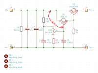
Here is @gtose 's schematic, lifted straight out of his post #477 which contained PCB Gerber files of the board layout which he generously donated.
I annotated the schematic in red, showing one possible DC voltage measurement that builders might (or might not) want to make, in the pursuit of ripple elimination with no oscilloscope. Naturally there many other possible measurements; I felt it might be useful to give this one a name.
_
I annotated the schematic in red, showing one possible DC voltage measurement that builders might (or might not) want to make, in the pursuit of ripple elimination with no oscilloscope. Naturally there many other possible measurements; I felt it might be useful to give this one a name.
_
Attachments

'... and suggest a voltage drop (measured from the input rail), that will ensure that the CapMX is working as intended ? "
Referring to the schematic that Prasi has provided , on post #989
R2 , the trimmer and R3 set up a voltage divider , and there is a voltage drop across Vbe1 and Vbe2 .
Suppose the 1K trimmer is set in the middle
Then Vout = Vin ( ( 500 + 10K) / 150 + 1K + 10 K ) - Vbe1 - Vbe2
Suppose Vin = 25 Vdc and the Vbe = 0.67 Vdc
This would give a drop out voltage of 2.8 v = 1.46 v + 0.67 + 0.67
So you are in the ball park .
For transistors , recommend selecting ones designed for audio applications because they have a low noise figure .
I am no expert on this , but 2n5551 and 2n5401 are quite good and easy to source .
MJE15032 and MJE15033 are also quite good , but these might be a bit small for your application .
.
Thanks U.
As an alternative can one say
V(J1-J3) = Q1 Vbe(on) + Q2 Vbe(on) + half the noise value + some overhead/wiggle room to accommodate variability of parts etc.
and use the data sheet values for Vbe for on conditions (1V and 1.5V).
so broad brush 1+1.5+0.1+0.1(?)
is this a reasonable approximation or is the similar value a coincidence?
As a follow up do you know what the variability is for these type of parts?
LTSpice has some optimal model but reality will vary from this by some amount. I'm just wondering whether its 0.1%, 1% or 10%
BerdyWan ,
Yes , see if you can find a used scope , it doesn't have to anything fancy .
I have basic old 50 year old scope . I'm not one for analogies , but trying to build an amp without a scope ,
is like trying to drive a car with a blindfold on . You can't see anything .
- Mark has graciously shown how to measure the amount of ripple with a DMM .
- What I've explained is how to calculate the the drop out voltage . The calculated value and measured value should be reasonably close .
- Noise is another issue . I've built a Fo Felix EMI filters and absolutely recommend adding one .
Haven't used Spice in years . But 2n5551 and 2n5401 are real basic audio transistors and Spice parameters
for these should be readily available .
.
noted and thanks.
The issue is not that I don't know how but that the DVM I have is old and either the noise ice well below spec, or my instrument is not sensitive enough to read the ripple component on the DC. I am aware of the Cordell models and have the models for the devices on the boards I have already built.
I agree a scope is the answer.
Have you considered using a sound card and REW to measure noise? (With appropriate DC blocking cap.) You can use the REW generator to generate a 0 dBFS sine wave that you then measure with your meter on RMS AC setting. Then use that voltage to calibrate the sound card ADC with the REW RTA in a loopback (sound card out to sound card in). Once calibrated you can use the REW RTA to measure noise.
If the sound card ADC is too noisy you can use an LNA. (That is more complicated but can be done.) A moving coil preamp design from Douglas Self is the basis of a 60 dB gain LNA that I use to measure noise along with an USB audio interface and REW.
Any chance you have a USB audio interface? Perhaps one with a low noise MIC input/preamp?
REW is nice for noise measurements because you can get a spectrum (in the audio band) of the noise.
I mention this since most people have a laptop or desktop with some sort of microphone input. (Usually pretty noisy, but some are pretty decent.) External USB sound interfaces can include pretty low noise mic preamps.
Depending on the noise level you want to measure maybe a fairly simple discrete microphone preamp design using a battery will boost the signal into a range that your meter can handle? Or maybe a simple NE5534 or NE5532 running from a battery can boost the signal enough for your meter?
Finally my first scope (at home, not work) was a DSO138. Not fancy at all but it definitely helped to be able to see what was going on at low frequencies. They are pretty affordable on Ebay or AliExpress.
Is there a gerber for a single supply version?wait, i will show you via a simple layout.
Edit:
ok here you go, hope it makes clear. mosfet has to be on a heatsink.
Thanks.
Is this one in post#862 at page 44😕Got it thanks!
https://www.diyaudio.com/community/...sy-capacitance-multiplier.297921/post-6615597
Please let me know, i want it for my JLH1969
page 10 Post #186, is it prasi&DJDestiny 😳Gebers Files.....
https://www.diyaudio.com/community/...itance-multiplier.297921/page-27#post-5533370Is this one in post#862 at page 44😕
https://www.diyaudio.com/community/...sy-capacitance-multiplier.297921/post-6615597
Please let me know, i want it for my JLH1969
Single rail fabrication results
I had the layout at http://www.diyaudio.com/forums/soli...sy-capacitance-multiplier-51.html#post5511885 fabricated at Elecrow. I ordered 10x 1.6mm/1oz/HASL for $5 before shipping (shipping was around $25). All design files, including Gerber and drill can be found at GitHub - oseaudiolabs/adjustable-cap-mx: Adjustable capacitance multiplier PCB.
I have not had time to do extensive testing or validation, but I am using it in my MoFo build detailed at http://www.diyaudio.com/forums/pass-labs/313649-build-mofo-139.html#post5531597. There does not appear to be any errors in the fabrication and layout, and the output voltage seems to track with the adjustment of the the trim pot. All of my testing has been with either a lab power supply or a well regulated SMPS, so the effect on power supply ripple has been hard to determine thus far. I did see a decrease in ripple on an SMPS (just using the AC voltage setting on my DMM) from around 4.1mV to 0.98mV at a 1A load. I have load tested up to a 6A on the SMPS without any noticeable issues with heat.
Next, I plan on testing it fed from an unregulated linear power supply. Hopefully this will let me validate a significant decrease in ripple and understand the impact of changes to the R2/RV1/R3 ratios. Does anyone have a better method to identify the actual ripple on the rails? Is using my DMM's AC setting enough or should I be inspecting with a scope?
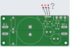
I'll make this single rail capmx of @gtose.
But I don't know what direction of Q1 (BD13910S).
Is it right pin direction?
Does Q1 need heat dissipation with heatsink?
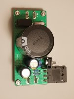
Actually, I soldered all parts already,
Attachments
Last edited:
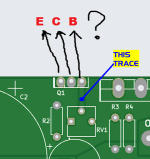
If you have access to the circuit schematic diagram, you could treat this question as a puzzle to be solved, a Brain Teaser of diyAudio:
Look at the indicated copper trace on the PCB layout (shown below). This trace connects the middle terminal of component "RV1" to the right hand terminal of "Q1". Now look at the schematic. Are there any connections on the schematic, between Q1 and RV1? If so, is RV1 connected to the Collector of Q1? Is RV1 connected to the Emitter of Q1? Is RV1 connected to the Base of RV1?
Now you simply combine this knowledge, with the pinout of the BD139 transistor as shown on the manufacturer's datasheet. Voila, the puzzle is solved. The transistor orientation has been deduced.
_
Attachments
MJ posted in #1003,OKI can't open this sch file from https://github.com/oseaudiolabs/adjustable-cap-mx
- Home
- Amplifiers
- Power Supplies
- Juma's Easy-Peasy Capacitance Multiplier