It's great to see the Epcos caps in the build but even these still suffer from 'overdone' - try using much, much smaller caps on the output like 100, 220 or 470uF and try the Nichicon Bipolar in place of the Panasonics - those bigger Epcos caps are excellent as primary filter caps - the whole behaviour/sound of the supply will be quite different
my 2 cents ...
Ok, advice noted, I have enough pcb to test another configuration.
Marc
I will have those 4x22.000uf 63V in CRC config in front of the two capmu
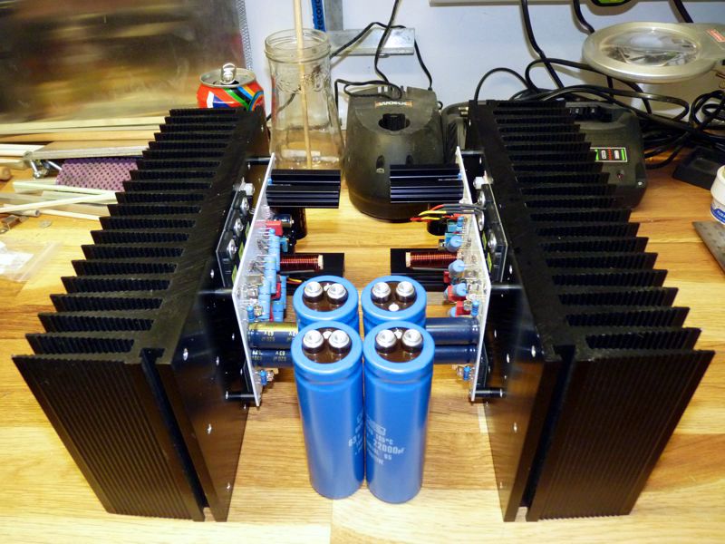
They are under the white board supporting 5W cement resistors
They are under the white board supporting 5W cement resistors
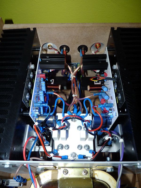
Hil X, the CAPMU Will be before cfh9. On picture it is the damaged Nbip. I re-use power supply and de with softstart and dc protect.
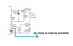
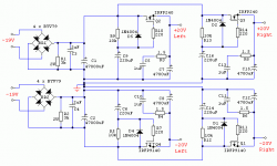
Can see down the road seems there was variables how good performance some builds and their layout gets, therefor share that in past we many time guided by specialists to get sense point as forward to load as possible maybe with remote wire, and performance will measure much better. Not specialist myself and have not lab gear to confirm but see below what was suggested to application as this and 78/79xx plus LM series, below schematic is half part taken from schematic into post 147

Attachments
Last edited:
Gebers Files.....
Marc
Hi,
I am have some problem trying to open the gerber files under the MCN Gerber viewer, do you experience the same thing?
Regards
You cab use the Sprint layout ....Sile> gerber importHi,
I am have some problem trying to open the gerber files under the MCN Gerber viewer, do you experience the same thing?
Regards
I have tried to open schematic in post#1, with different browsers but to no avail. Curious what's behind that closed door 🙂 , Anybody...
Try "gerber viewer on line" in google. The file a post above are those were send to board house to produce my board showned in the topic.
Marc
Marc
post1 contains both DIYaudio served pics and links to a private server that you need to be a Member of before you can gain access.
I don't know why he did that.
The third link takes me to post681. I think the address in the link is incorrect.
I don't know why he did that.
The third link takes me to post681. I think the address in the link is incorrect.
I have tried to open schematic in post#1, with different browsers but to no avail. Curious what's behind that closed door 🙂 , Anybody...
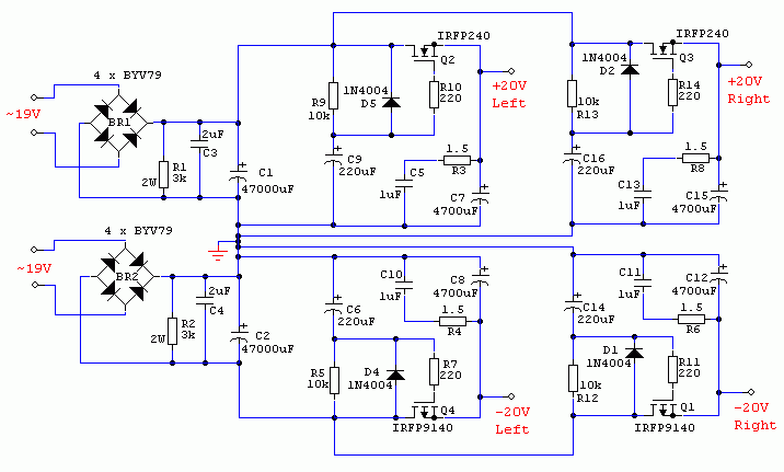
I did not know folks can't see the schematic. Here it is reposted from DIYA server.
Attachments
Again thank you guys! XKR for reposting, and Andrew for explaining and links and Marc for the gerber files. Now I can check if I made the translation from the gerber files to this schematic correctly.
I just put another Easy Peassy Cap Mx into my SE Class A headamp. Using IRF540 MOSFET for 20v output. Fed by XL6009 step up DC-DC converter.
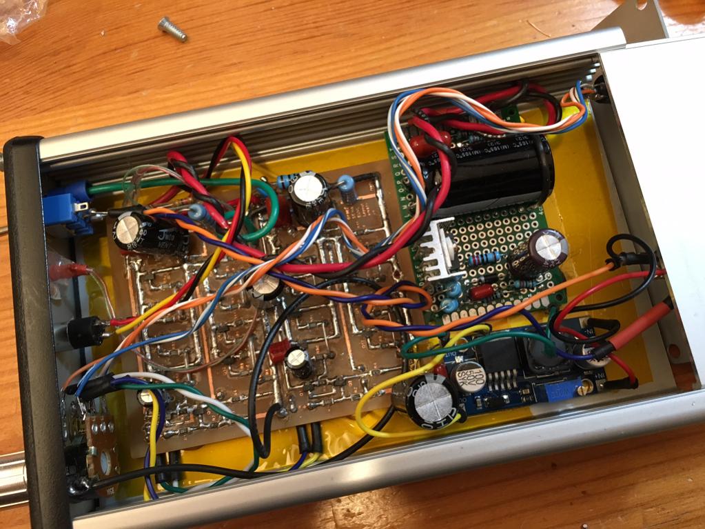
Bass authority seems to have improved noticeably. Amp was already quiet and now absolutely dead quiet.
Particulars: IRF540, 10k & 220uF cap and feedback, 1N4007 protection diode, 220R gate stopper, 1uF 230v MKT and 1.1R snubber, 10mF 25v output reservoir cap. Takes about 20 seconds to slowly turn on - so it's a nice soft-start feature to avoid turn on/off thump. Since current is only 100mA, using local heatsink for 400mW.
Last edited:
Isn't it great that those convertors do actually work - I've always been a bit hesitant because of the expected 'noise' but .....
This may sound a bit weird but try replacing that 10,000uF cap with maybe a 2,200uF one or even a 470uF, particularly if you happen to have those Nichicon BPs (the green ones)
As you have noticed, there's a whole variety of C-multipliers - one that's not often seen these days is the 2 transistors in series version- not sure where details would be now but some other reader might be able to locate it
I just built one with C9=470uf , C7=4700uf and R3=4.7R, I am using that to power my class-D amp, the capmu just gets little warm, roughtly about 3V drops, will try with smaller cap value and see if that affect the sound. Thanks for the circuit.
I tried using with various size uF caps on the Cx which im drawing +/-18V at 5amps per rail for a total of 10 amps per class A monoblock. Later it was simmed and showed maybe an improvement of 1 maybe 2 db across the audio band. I just went with low esr caps and on C7 I paralled 5 x 1000uF, just because...
I have builted Juma 's cap multiplier (post 1) with a very good results for my headphone amp. I just wondering if these is any circuit that work the same way for high voltage applcation? (150-250v)
Thank
Thank
I have builted Juma 's cap multiplier (post 1) with a very good results for my headphone amp. I just wondering if these is any circuit that work the same way for high voltage applcation? (150-250v)
Thank
I think the difficulty may lie in getting HV caps - look for industrial motor run caps which are 50uF and 250v or 450v even.
Vishay makes a 600v n channel MOSFET in TO247 package:
http://www.vishay.com/docs/91473/sihg22n60e.pdf
There may be a lack of P channels so basically make two identical N channel cap Mx and connect in series to get positive/negative.
- Home
- Amplifiers
- Power Supplies
- Juma's Easy-Peasy Capacitance Multiplier