I take it you have 2 separate loudspeakers, with one amplifier in each one? If so then you really are at one cap-mx per side. if the amp is in a separate stand alone box then maybe you'll be OK. You'll be fine with 2 x 22kuF - thats what I used. If you use mosfets you'll likley end up with 4-5V drop. If you use power BJT then maybe you would have a little less, maybe 2.5-3V or so.
The other thing is dealing with how hot the mosfets or BJTs might get, depending on the current draw. The more voltage you drop/current passes through then they will get a bit warmer, but they don't need a huge heatsink in general, but do need something. If this was an ordinary amplifier, I'd say to use the chassis floor etc as the heatsink.
The other thing is dealing with how hot the mosfets or BJTs might get, depending on the current draw. The more voltage you drop/current passes through then they will get a bit warmer, but they don't need a huge heatsink in general, but do need something. If this was an ordinary amplifier, I'd say to use the chassis floor etc as the heatsink.
I'm using two Prasi/Gtose/MJohnson Cap Mx in an M2 clone build. They are powered by two SMPS and everything works fine.
Now in the final assembly of the amp, I'd like to add two blue LEDs on the faceplate of the amp and intend to power the LEDs from the Cap Mx positive outputs and using resistors for the LEDs. Since the positive output have an additional load in the form of the LED and resistor (approx. 1K calculated), I'm wondering if I might run into problems having "unbalanced POS and NEG outputs. Is there a way in the design of the Cap Mx to adjust the POS output to the same voltage as the NEG output?

Now in the final assembly of the amp, I'd like to add two blue LEDs on the faceplate of the amp and intend to power the LEDs from the Cap Mx positive outputs and using resistors for the LEDs. Since the positive output have an additional load in the form of the LED and resistor (approx. 1K calculated), I'm wondering if I might run into problems having "unbalanced POS and NEG outputs. Is there a way in the design of the Cap Mx to adjust the POS output to the same voltage as the NEG output?
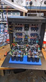
So, just a thread update. I fitted two of these (followed by a cap bank in CRC) to an Aleph 60 build - these are the ones back up the thread a little. Under full load, the noise is tiny at the capMX down to as low as the scope will go. No hint of the oscillation that I posted about above. The transistors (2sc5200/2sa1943) don't get very hot - I just have them bolted to the back plate of the amp which is just 3mm alu plate. That gets to 40degC or so. Each rail is pulling 2.5A so heavy enough load.
Attachments
Hi Prasi! Pls help share single rail gerber 🙏 both R&L on one pcb 😁🙏Here is an option with just removing the diode bridge and keeping everything same. As you mentioned, the diode bridge can be external '35A chassis mount' ones. Although this arrangement can be made with earlier layout as suggested by you.
If fun 🤩 diy 2SA5200 + BD139 😂 schematic Prasi!
https://github.com/oseaudiolabs/adjustable-cap-mx
From post #523

cant download gerber hehehe
Those are text files. Open each file on Github and copy the contents into files of the same name.
The Aleph 60 is a Class A amp. From my understanding Class A amps have a constant current draw and therefore they do not benefit much from a cap bank. Just a Cap Multiplier (and CRC?) should suffice.So, just a thread update. I fitted two of these (followed by a cap bank in CRC) to an Aleph 60 build
Hi people,
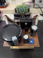
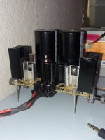
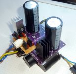
now I built this with IRFP240/IRFP9140. 2x 10000µF/75V, 2x 4700µF/63V + 2x 4700µF/63V. Same Transformator as before. It takes several minutes until the voltage is at the maximum of +/- 57V. Theres not much room for mistakes and I cannot find any. Everything stays cool. Is this normal?
regards
J.
now I built this with IRFP240/IRFP9140. 2x 10000µF/75V, 2x 4700µF/63V + 2x 4700µF/63V. Same Transformator as before. It takes several minutes until the voltage is at the maximum of +/- 57V. Theres not much room for mistakes and I cannot find any. Everything stays cool. Is this normal?
regards
J.
Attachments
The temp depends on how much current you are flowing. Power dissipated is I x V. V is about 4v for a MOSFET cap Mx. So about 4W for 1A current. Those heatsinks won’t handle more than 2-3W. If you were running an average Class A amp that draws 1.5A to 3A then 6W to 12W and you’ll need to mount the MOSFETs to a larger heatsink. Those diodes will need heatsinks if Class A as they dissipate I x 0.6v.
Maybe you understood me wrong. My question is: is it normal, that it takes about 10 minutes until I can measure the maximum rectified voltage of +/- 57V at the output of the CapMultiplier? The small coolers are just for testing, and the statement "everything is cool" was ment as, nothing gets hot because of a part soldered in wrong direction/placement/size (biggest cap I ever blew up was a 470µF/35V. I don't want to experience this with a 4700 or 10000µF, so I look 3x for the right polarity) . That flowing current will heat up the Mosfets which control the flow should be clear, even to me.The temp depends on how much current you are flowing. Power dissipated is I x V. V is about 4v for a MOSFET cap Mx. So about 4W for 1A current. Those heatsinks won’t handle more than 2-3W. If you were running an average Class A amp that draws 1.5A to 3A then 6W to 12W and you’ll need to mount the MOSFETs to a larger heatsink. Those diodes will need heatsinks if Class A as they dissipate I x 0.6v.
It should reach voltage within 45 seconds or so based on RC time constant of the parts in the schematic. 10min is way too long. Are you off by a factor of 10 on the resistor?
The cap being “multiplied” is the 220uF at the gate of the MOSFET and the 10k is charging it. If you are using 4700uF and 10k that’s 21x longer so 10min would make sense. Change the cap to smaller value. No bigger than 470uF.

The cap being “multiplied” is the 220uF at the gate of the MOSFET and the 10k is charging it. If you are using 4700uF and 10k that’s 21x longer so 10min would make sense. Change the cap to smaller value. No bigger than 470uF.
Last edited:
Thank you very much! This sounds comprehensible. I misunderstood the schematic along with the layout.
I have put together a few copies of BJT versions of this capacitance muliplier (with some BC5xx smd transistors and BD139/140 and D44H110). I use 2 of them in my EUVL's UTHAiM headphone amplifier and one in Pass B1 preamp. I find them actually pretty dark sounding. I will not speak about UTHAiM as I have not tried any other power supply with it. But I did try a number of PSUs with B1. I have tried a simple LM317 regulator, SMPS 19V (Lenovo rated at 5A) and the multiplier.
I have found LM317 pretty bright which might be caused by some peak in the output impedance (I used 470uF output capacitor). Then I though I would try the SMPS as Nelson prescribed. That was a big improvement.
Then I tried the xcap just because I had a few PCB lying around. As I say the sound is so much darker compared to SMPS (mind I still have 15000uF after 1Ohm resitor on the B1 board!) The thing is I am worried that some frequencies are sucked out. Some vocals are clearly recessed compared to SMPS. I would like to understand this a bit more. Can anybody shed some light or tell me something is wrong in my setup? Or suggest tests I can run?
Is it a SMPS with a CLC filter (Sony VFET amp) you are comparing to?Then I though I would try the SMPS as Nelson prescribed.
- Home
- Amplifiers
- Power Supplies
- Juma's Easy-Peasy Capacitance Multiplier