What if, you inkrease the source impedance to 400ohm to simulate an transconductance amplifier. How would that affect the distortion?
I have experimented with transconductance amplifiers for subwoofers, with good results.
I have seen others that have measured 20dB decrease in distortion of the speaker.(acoustic measurement…)
I have experimented with transconductance amplifiers for subwoofers, with good results.
I have seen others that have measured 20dB decrease in distortion of the speaker.(acoustic measurement…)
With luck I'll be able to get some measurements this week. I have moved a lot of junk out of the way.
That would be great.
What if, you inkrease the source impedance to 400ohm to simulate an transconductance amplifier. How would that affect the distortion?
I have experimented with transconductance amplifiers for subwoofers, with good results.
I have seen others that have measured 20dB decrease in distortion of the speaker.(acoustic measurement…)
For an electromagnetic speaker it makes sense to be current driven, since force on the cone is F=B*I*L*sin(a).
No voltage is in the equation, just current I.
A transformer on the other hand is basically a voltage converter.
For the ESL current drive would prevent core saturation of the transformer to some degree, but the FR would follow the wildly varying impedance, that is also very level dependent, most unwanted.
Hans
I have started a build (over 10 years ago... and not finished... hands up if you recognice the situation) with a "direct driven Quad electrostatic speaker.
2 x GM70 tubes with 1200volt power rail and capacitor coupled transformers with 1:3 in step up ratio. Mr Brian Sowter made the 4 transformers to me as well as power supply transformers.
Anyway, my idea was to use a voltage divider on the secondary to feedback the GM 70 tubes.
Now, when i see the distortion from the tranformers i guess thats a good idea.
Another idea that i get right now is if you will gain of using double transformers in parallell in a ESL 63 to keep the currents in half and by that reduce distortion?
Also there is some resistors in series today, can you simulate the distortion without those?
(i have removed them many years ago, it sounded better)
It would be way simpler to add feedback around the transformers. You could also borrow AP's distortion cancelling circuit for transformers. US4614914A - Low-distortion transformer-coupled circuit
- Google Patents I have never seen it used in a power device but no reason why it would not work. And with Quad's the load is completely predictable.
- Google Patents I have never seen it used in a power device but no reason why it would not work. And with Quad's the load is completely predictable.
It would be way simpler to add feedback around the transformers. You could also borrow AP's distortion cancelling circuit for transformers. US4614914A - Low-distortion transformer-coupled circuit
- Google Patents I have never seen it used in a power device but no reason why it would not work. And with Quad's the load is completely predictable.
yes , feedback around the transformaer was what i meant.
Yes of course, doubling the amount of transformers will reduce the current.Another idea that i get right now is if you will gain of using double transformers in parallell in a ESL 63 to keep the currents in half and by that reduce distortion?
Also there is some resistors in series today, can you simulate the distortion without those?
(i have removed them many years ago, it sounded better)
But keep in mind 2 things:
1) at 12Volt 20Hz, distortion is only 0.8%, and it's going down with 20dB/decade giving 0.08% at 200Hz and so on.
This is extremely fantastic, better than any electromagnetic speaker.
2) the previous results shown at 10Hz 30V pk are under the assumptions that I have made for the transformer, which may improve considerably when new data is collected.
Only the 1% at 6V@10Hz is correct, everything above is uncertain.
So for the time being, a good subsonic filter seems like a better investment.
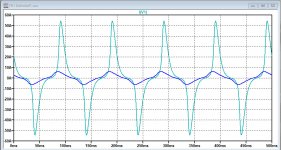
Removing the two 1.65R resistors seems like a very bad idea since they limit the current through the transformers.
See the image below showing the current flowing with and without the 1R65 resistors for a 20V pk input signal at 10Hz.
Hans
Attachments
Looking forward to seeing results of your detailed LTspice Model...I just used a number of assumptions to be refined at a later stage, like length of the magnetic path of 2pi*3cm, no air gap, a cross section of 2.5cm^2 and common used value for Hc and Bs for the (silicon steel ?) core material.
With just 2 remaining variables, Br and the number of turns N on the primary, I steered to get a primary inductance of 250mH and a distortion of ca.1% at 10Hz with a 6 volt input voltage
")
Until you get the opportunity to measure a transformer for yourself, I can provide some values I had measured/estimated for a few of the items.
- Np = 48 (number of primary turns)
- A = 13cm^2 (core cross-sectional area)
- LP = 16cm (magnetic path length)
These match up fairly well with some numbers posted by JonasKarud a decade ago. ESL Diaphragm coating
The only one that is noticeably different is the magnetic path length which he has as 200mm.
I think that number must be based on the other dimensions of the cores, not the centerline dimensions.
Using the BH curve for M6 grain oriented transformer steel should get you close.
Steve,Looking forward to seeing results of your detailed LTspice Model
Until you get the opportunity to measure a transformer for yourself, I can provide some values I had measured/estimated for a few of the items.
- Np = 48 (number of primary turns)
- A = 13cm^2 (core cross-sectional area)
- LP = 16cm (magnetic path length)
These match up fairly well with some numbers posted by JonasKarud a decade ago. ESL Diaphragm coating
The only one that is noticeably different is the magnetic path length which he has as 200mm.
I think that number must be based on the other dimensions of the cores, not the centerline dimensions.
Using the BH curve for M6 grain oriented transformer steel should get you close.
Thanks for this information.
I will adjust my model accordingly and report the results.
Hans
Hans Polak when i read about the design Baxandall describes the mutual inductance between each coil. This means that you need to measure on the complete setup of inductors. Basicly the easiest way would be to measure on the complete speaker...
True, but for the moment I'm just concentrating on the Trafo.
Coil will be the next step, thanks anyhow.
Hans
The dead panels finally arrived and I had a chance to measure the capacitance-
These are for 1 panel so the actual load on the network would be 2X. Looking at the panel these numbers make sense wrt the area connected.
I saw no change with frequency from 100 Hz to 100 Khz.
Woofer panel- 152.5 pF
Tweeter from center to edge-
11.5 pF
12.2 pF
12,2 pF
14.4 pF
14.5 pF
15.5 pF
53.8 pF
23.3 pF
Steve,
How sure are you concerning the 48 turns primary.
When I use this with a Hc=30 and Bs=2.0, which can't be that far off, I get a transformer which is distorting like hell in the LF area.
Impossible to get 1%@10Hz@6Volt.
Hans
I found the link you gave, so these winding numbers seems correct.
Will experiment a bit further with other core materials.
Hans
That's great, thank you.The dead panels finally arrived and I had a chance to measure the capacitance-
These are for 1 panel so the actual load on the network would be 2X. Looking at the panel these numbers make sense wrt the area connected.
I saw no change with frequency from 100 Hz to 100 Khz.
Woofer panel- 152.5 pF
Tweeter from center to edge-
11.5 pF
12.2 pF
12,2 pF
14.4 pF
14.5 pF
15.5 pF
53.8 pF
23.3 pF
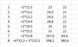
When I interpret your figures correct, the third column shows what I get for the 8 panels.
Last column is what I used up to now, I will correct these numbers in my LTSpice sim.
Hans
Attachments
How sure are you concerning the 48 turns primary.
When I use this with a Hc=30 and Bs=2.0, which can't be that far off, I get a transformer which is distorting like hell in the LF area.
Impossible to get 1%@10Hz@6Volt.
I am quite certain of the primary turns count= 48 and the core area of 13cm^2.
The magnetic path length I didn't measure as carefully, but should be within 10%.
If I understand the measurement in the Dutch review, they put a 1 ohm resistor in series between the amplifier and the speaker terminals. Then they measured the voltage across speaker terminals. Is this what you are simulating in your distortion measurements?
I’m also convinced that it was a reliable count from Jonaskarud giving 49 prim. turns.I am quite certain of the primary turns count= 48 and the core area of 13cm^2.
The magnetic path length I didn't measure as carefully, but should be within 10%.
If I understand the measurement in the Dutch review, they put a 1 ohm resistor in series between the amplifier and the speaker terminals. Then they measured the voltage across speaker terminals. Is this what you are simulating in your distortion measurements?
So far I measured on the secondary, but switched to the Danish way with 1R in series, but I do not get even close with silicon steel when trying to get 250mH and 1%@10Hz@6Volt.
Could it be that the core is from a ceramic composition ?
Hans
Last edited:
- Home
- Loudspeakers
- Planars & Exotics
- QUAD 63 (and later) Delay Line Inductors