Look, coercive force is around 40 A/m and remanent magnetization or remanence could be as high as 1T for GOSS so forget about it.
With luck I'll be able to get some measurements this week. I have moved a lot of junk out of the way.
Hi Demian,
After that you have measured the membrane capacitances so accurately, do you see any possibilities to measure the transformer and/or the delay line inductor with your Bode 100 in the near future ?
It would be great if this project could be finalized as close to the real thing as possible.
Hans
Last edited:
I'm still clearing out junk in the shop to make room (Stygian sables reference goes here). I'll target some measurements this week. It will be an interesting project.
I'm still clearing out junk in the shop to make room (Stygian sables reference goes here). I'll target some measurements this week. It will be an interesting project.
Great, I almost can’t wait,
Hsns
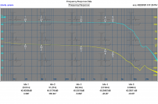
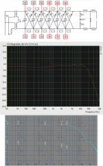
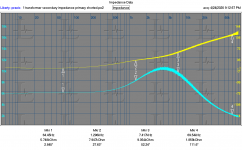
Partway through the setup. Attached is the forward response of the transformer itself in circuit. I'm measuring from XFMR input terminals to XFMR output terminals with a pretty small signal (200 mV). I need to build some probes to handle the HV and also look at whether the BODE100 would show something this doesn't.
Attachments
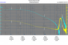
Here are plots with the delay line connected and disconnected.
Also the probe in this case is approx 100K. I'll try to make a useable probe that gives an X100 response. It won't be that simple with the high voltages, but I could then drive with some significant signal and measure distortion.
Also the probe in this case is approx 100K. I'll try to make a useable probe that gives an X100 response. It won't be that simple with the high voltages, but I could then drive with some significant signal and measure distortion.
Attachments
Hi Demian,
Great that you have already spent some time in measuring and producing some interesting images.
But to be honest, I still have a bit of a problem to understand these graphs.
What is the blue line and the same question for the yellow line.
Are these 2 resp. input signal versus output from your 100K HV probe, and is this all without the 1R65 and 1R5//220uF at the input ?
And what is the red line in the last image ?
You are still working on a 100K secondary probe.
This will mean the equivalent of 1R7 at the primary !
When measuring a xmfr with your Bode as in posting #54 you won't need a high voltage probe, but you are most likely aware of that.
Looking forward for additional data.
Hans
Sorry for not proving some details to help explain the plots.
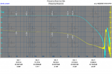
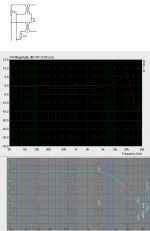
On the last plot which goes from 1KHz to 100 KHz the red trace is the voltage ratio of the transformer measuring input to output with only the 100K (maybe 50K) of the differential probe of the Praxis across it.The Teal trace is the same with the delay line connected. The Yellow trace is the phase relationship between input and output with the delay line connected.
I'm not sure how you get 1.7 Ohms at the primary. The plot shows the 100X turns ratio and the impedance transform is the square root of the turns ratio or 10K I believe.
I'm using Praxis because its useable as a full 2 port differential network analyzer here. In these plots I'm using a headphone test amp to drive the system since its wahat is connected. I'll be building an HV probe interface for the Praxis today. That will allow me to drive the transformer at higher levels with a test amp and see what comes out. If the connections were easier to get to i would also look at the delay line outputs but they are buried.
The max in on the Bode is listed at 50V before damage and the source Z is 50 Ohms. I'm not ready to risk that yet. Maybe if I can interface a differential HV probe I have.
Thanks for your answers, now I know the difference between teal and yellow.Sorry for not proving some details to help explain the plots.
On the last plot which goes from 1KHz to 100 KHz the red trace is the voltage ratio of the transformer measuring input to output with only the 100K (maybe 50K) of the differential probe of the Praxis across it.The Teal trace is the same with the delay line connected. The Yellow trace is the phase relationship between input and output with the delay line connected.
I'm not sure how you get 1.7 Ohms at the primary. The plot shows the 100X turns ratio and the impedance transform is the square root of the turns ratio or 10K I believe.
I'm using Praxis because its useable as a full 2 port differential network analyzer here. In these plots I'm using a headphone test amp to drive the system since its wahat is connected. I'll be building an HV probe interface for the Praxis today. That will allow me to drive the transformer at higher levels with a test amp and see what comes out. If the connections were easier to get to i would also look at the delay line outputs but they are buried.
The max in on the Bode is listed at 50V before damage and the source Z is 50 Ohms. I'm not ready to risk that yet. Maybe if I can interface a differential HV probe I have.
But I'm still not sure what and how you are measuring.
I suppose you are driving both transformers because you measured with and without delay lines, which can hardly be done with only one transformer.
So are you indeed driving both transformers but measuring on the output of just one, and is the drive signal for the teal line applied with the 1R65 resistors and the 1R5//220uF still in place, and was then measured between secondary and gnd ?
And for the red line was your differential probe connected on one side to the primary and with the other side to the secondary ?
The supposed ratio of the XFMR is 120, or 41.6dB, which is more or less the case with your red line.
When connecting a 100k probe to the secondary with a gain of 240 for both transformers, 100K / (240)^2 = 1R7, that's how I calculated this.
In case of just measuring the output of one transformer this will give 100K/(120)^2 = 6R9.
Why do you bother about the voltage the Bode can generate ?
Applying one or two Volt max and a few steps below will be more than enough to measure the transformer.
You only have to measure an isolated transformer open ended and short circuited, as in posting #54.
Hans
Last edited:
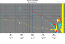
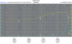
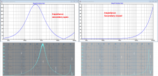
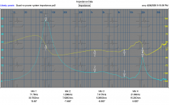
Here are measurements of 1 transformer. I disconnected one primary wire and the delay line for these measurements.
1) primary impedance secondary shorted
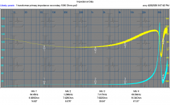
2) primary impedance secondary terminated with 100K Ohms
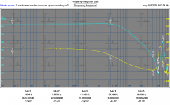
3) Transformer response "gain" and phase.
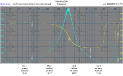
4) primary impedance secondary open
The primary impedance with the secondary terminated with 100K is around 8 Ohms, which sort of makes sense. I was wrong there. The turns ratio is much closer to 100. The measurement suggests a ratio of 106 to 1.
Do you need secondary impedance measurements the same way? I can also provide the discrete data files.
Getting to delay line coils is not happening here. They would require a lot more disassembly of the working parts of this speaker. Its owner is expecting it to work again.
I can measure the secondary distortion VS. frequency tomorrow after building the HV probe.
I need to reassemble the speaker soon. These are a PITA to balance upside down for any length of time.
1) primary impedance secondary shorted
2) primary impedance secondary terminated with 100K Ohms
3) Transformer response "gain" and phase.
4) primary impedance secondary open
The primary impedance with the secondary terminated with 100K is around 8 Ohms, which sort of makes sense. I was wrong there. The turns ratio is much closer to 100. The measurement suggests a ratio of 106 to 1.
Do you need secondary impedance measurements the same way? I can also provide the discrete data files.
Getting to delay line coils is not happening here. They would require a lot more disassembly of the working parts of this speaker. Its owner is expecting it to work again.
I can measure the secondary distortion VS. frequency tomorrow after building the HV probe.
I need to reassemble the speaker soon. These are a PITA to balance upside down for any length of time.
Attachments
-
 Quad transformer primary impedance secondary shorted.PNG71.7 KB · Views: 218
 -
 Quad transformer primary impedance secondary terminated with 100K ohms.PNG73.9 KB · Views: 108
 -
 transformer response secondary terminated with Praxis probe.PNG74 KB · Views: 112
 -
 Quad transformer primary impedance secondary open.PNG77.5 KB · Views: 102
Here are measurements of 1 transformer. I disconnected one primary wire and the delay line for these measurements.
1) primary impedance secondary shorted
2) primary impedance secondary terminated with 100K Ohms
3) Transformer response "gain" and phase.
4) primary impedance secondary open
The primary impedance with the secondary terminated with 100K is around 8 Ohms, which sort of makes sense. I was wrong there. The turns ratio is much closer to 100. The measurement suggests a ratio of 106 to 1.
Do you need secondary impedance measurements the same way? I can also provide the discrete data files.
Getting to delay line coils is not happening here. They would require a lot more disassembly of the working parts of this speaker. Its owner is expecting it to work again.
I can measure the secondary distortion VS. frequency tomorrow after building the HV probe.
I need to reassemble the speaker soon. These are a PITA to balance upside down for any length of time.
Demian,
The reason I keep asking what and how you made your measurements, is simply because your results are so far from the earlier results that Steve published in posting #19.
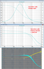
For that reason I have tried to put both results together, 1) FR with no load and 2) FR with the delay and membranes connected.
Your images are resp. from posting #110 where your third image shows the FR with secondary open and from posting #105, measured in circuit with delay lines etc attached.
I have tried to match the frequency scaled of your images with Steve's images for easier reading and only displayed level and no phase.
As you can see, in Steve's images loaded level is only a few dB down at 20kHz, whereas in your images level at 20khz is 15dB down.
And in your image the unloaded resonance peak is completely absent.
Also because Steve's images match within one or two dB's with my LTSpice model, I get the impression that something is wrong here, either with the tranformer or with your measurement gear.
Hans
Attachments
Last edited:
Demian,
This is when comparing your measured impedance results versus the transformer model I have in LTSpice.
Apart from the differences at 55kHz, they are much closer than the FR images.
But to calculate inductance, reactance and resistance, I need more than just these images.
Do you have happen to have CSV files from these recordings, and also the level of the applied voltage plus the value of your measuring resistance in series with the transformer (50 Ohm ?).
With these CSV files I could work out the missing info's.
Hans
P.S. And yes, if you could measure from the secondary side with the primary open and closed, that would give yet another piece of information
Attachments
Last edited:
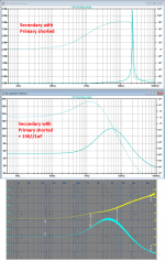
Here is the secondary impedance with the primary open and shorted.
I also remeasured the system impedance with this setup at the external terminals to check against the previous measurement
The system is using a 2V signal through 100 Ohms for these measurements.
I'll switch to a different drive setup and hopefully have my HV probe (10 Meg on each differential in) up and running later tomorrow or Sunday. I'll duplicate some of these measurements to validate them with different equipment.
Then I'll zip everything into one large file with hopefully descriptive names.
Attachments
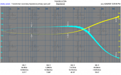
I'm totally puzzled how this result on the Secondary should be interpreted.Here is the secondary impedance with the primary open and shorted.
I also remeasured the system impedance with this setup at the external terminals to check against the previous measurement
The system is using a 2V signal through 100 Ohms for these measurements.
I'll switch to a different drive setup and hopefully have my HV probe (10 Meg on each differential in) up and running later tomorrow or Sunday. I'll duplicate some of these measurements to validate them with different equipment.
Then I'll zip everything into one large file with hopefully descriptive names.
It's way ahead of what is to be expected.
With the primary open, you have a series resistance of 1350 Ohm, a secondary coil of ca 3600H par to a 35pF cap.
At 5Hz, impedance should start at ca. 120k and have a resonance peak at [1/2*pi*sqrt(3600*35pF)] = 450Hz
But to get the impedance images you provided, I have to add 12K // 1nF parallel to the secondary !!
Would it be possible to do the four measurements with your Bode 100 , resp from prim with sec open/shorted and from the sec with the prim open/shorted , and send me the CSV files.
Then I can do all the data analysis.
Let's just concentrate on the transformer itself, when connected to the delay lines there are far too many variables diffusing the results.
Hans
Attachments
Last edited:
I measure 2993 Ohms DCR for the transformer secondary I measured and 3138 Ohms for the other transformer in this speaker. Its quite different from the 1.3K you mentioned. This is with two DMM's. I may have another way to measure them since large inductors can really screw with DMM Ohms circuits.
I measure 2993 Ohms DCR for the transformer secondary I measured and 3138 Ohms for the other transformer in this speaker. Its quite different from the 1.3K you mentioned. This is with two DMM's. I may have another way to measure them since large inductors can really screw with DMM Ohms circuits.
Sorry, I was wrong. In my model this resistor is 3560 Ohms.
With that resistor and the 3600H coil, impedance should be 120K at 5Hz, that part was correct and goes way beyond the value of this resistor.
(imp=jwL is ca 2*3.14*5*3600=113k)
The 3600H and the 35pF must also be close to what you will have, hence the Fres of ca 450 Hz that is missing in your image with open ended primary.
Hans
Last edited:
I'll see if I can move a bridge close enough to measure the secondary inductance. That will be a bit involved.
In the left image of posting # 114, the one in the middle says “primary shorted”
This should of course be primary open.
All three are for primary open and the image at the right is for all three with the primary shorted.
Hans
This should of course be primary open.
All three are for primary open and the image at the right is for all three with the primary shorted.
Hans
I switched to the Bode and collected the same data except the lowest it goes is 100 Hz and I stopped at 1 MHz figuring info up to 50 MHz is not useful.
This is super fantastic, thank you.
I'll go through all the data tomorrow.
I assume you used a 50 Ohm in series with the transformer, right ?
Hans
- Home
- Loudspeakers
- Planars & Exotics
- QUAD 63 (and later) Delay Line Inductors