Bolsert,
While I was working on my posting, your version preceded mine.
Many thanks for all the info, I will have a close look at it and where necessary integrate this in my LTSpice model.
Hans
While I was working on my posting, your version preceded mine.
Many thanks for all the info, I will have a close look at it and where necessary integrate this in my LTSpice model.
Hans
Bolsart,
A few questions on your excellent work if you allow me:
1)Do the values for the audio transformer that you supplied refer to one single transformer, or did you measure the set of two as one big transformer.
When regarding this as the data for just one transformer, I get 2 times 1.48H in the secondary, which seems too much, leading to a sharp rise of the impedance above 20Khz.
When regarding your data to be valid for the combination of the two audio transformers, I just get one single 1.48H or two 0.74H inducters which seems O.K.
2) The 35pF secondary cap that you specify is a bit of a mystery to me.
Should this not be the capacity between the primary and the seconday winding ?
Hans
Finally located the measurements I took back in 2016....
That's a huge service & of interest to the rest of us - many thanks!
Steve,
I would stil like to get some of your support in knowing how you defined your transformer data.
Was the data provided for just one transformer, so the Main Amp sees 2x par. 250mH=125mH with a total gain of 244, or did you measure both as being one big transformer making the main amp see 250mH with a total gain of 122.
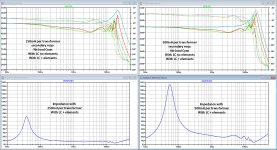
In the image below, I have shown for both possibilities the FR and the Impedance.
However I had to increase the secondary 3K65 resistor to 65K for FR and Impedance versions to get the same unloaded FR with 7.5dB peak around 20 Khz as you showed, and also the impedance needed this higher value to keep it from getting too low around 20Khz.
You also see a rapid rise in impedance above 20Khz that is steeper than the real ESL63 is showing, that could mean that the 1.48H leakage may be a bit too large ??
But even with the unloaded FR curve being the same as in your picture, I still see rather large differences with the loaded FR.
Do you still have some additional ideas ?
Hans
I would stil like to get some of your support in knowing how you defined your transformer data.
Was the data provided for just one transformer, so the Main Amp sees 2x par. 250mH=125mH with a total gain of 244, or did you measure both as being one big transformer making the main amp see 250mH with a total gain of 122.
In the image below, I have shown for both possibilities the FR and the Impedance.
However I had to increase the secondary 3K65 resistor to 65K for FR and Impedance versions to get the same unloaded FR with 7.5dB peak around 20 Khz as you showed, and also the impedance needed this higher value to keep it from getting too low around 20Khz.
You also see a rapid rise in impedance above 20Khz that is steeper than the real ESL63 is showing, that could mean that the 1.48H leakage may be a bit too large ??
But even with the unloaded FR curve being the same as in your picture, I still see rather large differences with the loaded FR.
Do you still have some additional ideas ?
Hans
Attachments
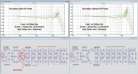
In the above image, the red line is with complete load and the green line with LC line but without elements
Could it be that the smoothing that Arta applies to your curves, let them look less zig zag ?
Hans
Could it be that the smoothing that Arta applies to your curves, let them look less zig zag ?
Hans
Last edited:
Instead of increasing the secondary 3K65 to 65K, I can also place a series resistor of 60k in the 35pF secondary cap and leave the 3K65 intact.
This gives better results in the FR and in the Impedance curve.
Will show te results tomorrow,
Hans
This gives better results in the FR and in the Impedance curve.
Will show te results tomorrow,
Hans
Finally located the measurements I took back in 2016. Thank again to stokessd for letting me borrow one of the interface units he was purchasing.
Man, I have no recollection of that, but it sounds like something a nice guy would do; and I'm clearly a nice guy so...
😀
I'm glad to help.
Sheldon
Sorry for the confusion. The parameters are for a single transformer. You can modify the primary inductance of each transformer as long as you modify the secondary inductance at the same time such that: LS = LP x N^2, where N=step up ratio = 122. Depending on the signal level, it could have a range of values, I just chose a nominal value when documenting the parameters. It will really only affect the LF response, so probably not of much importance for your effort. Attachment #1 is screen grab of a spice model I made back in 2016 when I was checking the measurements. It looks to match pretty well. One thing I notice is that I added in a source resistance of 0.3 ohm, which sounds like a reasonable value for all the connections and wiring between amplifier and my test setup. Looks like I also added in about 10pF of stray capacitance to account for other capacitive loads seen by HV windings not related to the winding capacitance(see response to next question below). Usually winding capacitance is so much larger than stray capacitance that it can be ignored, but the ESL63 transformer is a unique design where such details can become important.…Do the values for the audio transformer that you supplied refer to one single transformer, or did you measure the set of two as one big transformer.
Interestingly(at least to me) if stray capacitance can be ignored, the frequency of the HF resonance is at the same frequency for two transformers (wired up per ESL63) as for one. The reason being that the both LL and CS are in series. So the net leakage inductance doubles but net winding capacitance halves, so the product is still the same...thus same resonance frequency.
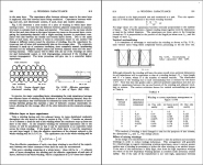
This is the self capacitance of the secondary winding which is made up of many layers. Basically each pair of winding layers acts like the plates of a parallel capacitor. With many layers, you have a group of capacitors in series. The net effect is a capacitive load on the secondary that resonates with the leakage inductance. Attachment #2 provides some details on winding capacitance. You can download the full book from here: http://www.tubebooks.org/Books/RDH4.pdf… The 35pF secondary cap that you specify is a bit of a mystery to me.
Should this not be the capacity between the primary and the seconday winding ?
The capacitance between primary to secondary winding is very small with the ESL63 transformer because the end of the secondary closest to the primary is grounded.
You probably already know this, but the coupling factor(K) is just another way to define leakage inductance. If you are including the leakage inductance(LL) as an inductive component in series with the secondary winding, then you should set K=1. Alternatively, you can remove the inductor representing LL and set K to a value that appropriately represents the amount of leakage inductance.… I have changed the coupling factor of the audio transformer from 1 to 0.9998.
The relationship between LL and K is:
K= sqrt(1-LL/LS)
As I mentioned previously, I haven’t done any modeling work on the LC transmission line. My work was geared toward understanding the transformer design. Based on review of the Baxandall treatise, I would guess that the differences you are seeing will likely come down to proper modeling of the shorted winding coupled to each of the inductors. This is mentioned to dampen and gently roll off the top end. See also text related to Figure 3. in Attachment #3. Really makes one appreciate Walker’s accomplishment from 40 years ago!…even with the unloaded FR curve being the same as in your picture, I still see rather large differences with the loaded FR. Do you still have some additional ideas ?
Attachments
Last edited:
You are very welcome.That's a huge service & of interest to the rest of us - many thanks!
I’m glad to hear there are people besides myself that find this interesting.
Ha! And I was surprised by how many measurements I found that I had done that I don’t remember taking. 😀Man, I have no recollection of that…

Steve,
Thanks for all your info's and the confirmation that your data concerned just one Audio transformer.
I could replicate your LTSpice sim, but also looked at your original measurement, showing a peak around 19kHz of +7.5dB with your HV probe connected.
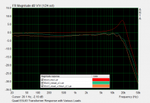
To get the same +7.5dB I had to add a small serial resistance of 13K to the secondary 35pF Cap.
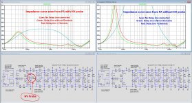
To show what a huge difference this 2.7Meg//5pF probe causes, I have made sims with and without this probe.
But I'm still faced with a large zig zag ripple when connecting the delay line.
So I will have to play around with the Delay Line Inductor.
When I had one to measure, It would be of great help.
One last question:
In your posting #19, the first attachment, You have shown the inductance of the secondary open transformer for a certain frequency while increasing the input voltage.
Why isn't the inductance flat up to the point where saturation starts ?
Hans
Thanks for all your info's and the confirmation that your data concerned just one Audio transformer.
I could replicate your LTSpice sim, but also looked at your original measurement, showing a peak around 19kHz of +7.5dB with your HV probe connected.
To get the same +7.5dB I had to add a small serial resistance of 13K to the secondary 35pF Cap.
To show what a huge difference this 2.7Meg//5pF probe causes, I have made sims with and without this probe.
But I'm still faced with a large zig zag ripple when connecting the delay line.
So I will have to play around with the Delay Line Inductor.
When I had one to measure, It would be of great help.
One last question:
In your posting #19, the first attachment, You have shown the inductance of the secondary open transformer for a certain frequency while increasing the input voltage.
Why isn't the inductance flat up to the point where saturation starts ?
Hans
Attachments
I think I'm done, thanks to all the excellent info's I got from Steve.
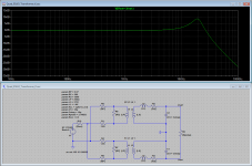
Getting the Zig Zag FR at HF under control was achieved by giving the Delay Line Inductor a Rpar=300K.
In the image below at the left side my sim including the HV prove that Steve also used in the image below from a real measurement.
These two images are as close as I can get.
At the right side the FR and the Impuls response for my LTSpice model but now without HV probe. FR looks very good and the step response nicely shows the delay per segment.
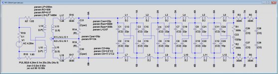
The second attachment shows the LTSpice model, and the third attachment the .asc file.
Hans
Getting the Zig Zag FR at HF under control was achieved by giving the Delay Line Inductor a Rpar=300K.
In the image below at the left side my sim including the HV prove that Steve also used in the image below from a real measurement.
These two images are as close as I can get.
At the right side the FR and the Impuls response for my LTSpice model but now without HV probe. FR looks very good and the step response nicely shows the delay per segment.
The second attachment shows the LTSpice model, and the third attachment the .asc file.
Hans
Attachments

The inductance increases with applied voltage because the permeability of the core increases with flux density which is proportional to the applied voltage. Most core materials that can handle high flux density before saturation have a much lower permeability at low flux density(often a 10 to 1 ratio or more). Attached are another couple pages from the transformer chapter of the book download linked to in post #28. In the table u0 = initial permeability = permeability for low flux density(ie small input voltage).…In your posting #19, the first attachment, You have shown the inductance of the secondary open transformer for a certain frequency while increasing the input voltage. Why isn't the inductance flat up to the point where saturation starts ?
Thanks for sharing the circuit file. Your results look too have the correct trends nowI think I'm done, …Getting the Zig Zag FR at HF under control was achieved by giving the Delay Line Inductor a Rpar=300K.

The shorted windings would load the delay line inductors predominately with a parallel resistance as you have done. Of course there would be other smaller parasitic effects (leakage inductance and winding capacitance) that would account for the remaining differences and small ripples. But, I’m not sure there is much else to learn by trying to match measurements more closely.
Attachments
Interesting to look somewhat deeper into this transformer area, thanks again for your info's.The inductance increases with applied voltage because the permeability of the core increases with flux density which is proportional to the applied voltage. Most core materials that can handle high flux density before saturation have a much lower permeability at low flux density(often a 10 to 1 ratio or more). Attached are another couple pages from the transformer chapter of the book download linked to in post #28. In the table u0 = initial permeability = permeability for low flux density(ie small input voltage).
Since I'm not a Tube man, but I suppose you are, I never paid them any attention before and I'm surprised in the huge differences between u0 and umax.
It's a perfect explanation why the impedance at frequencies is so much dependent on level.
I measured quite a lot of MM Cart's over a very large spread of levels and never noticed but a minimal change in inductance.
The explanation can only be that B/H was still around u0 all the time, that's the reason why I was a bit surprised by your graphs.
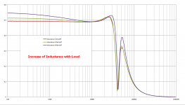
See level versus inductance in the two images below for a Ortofon super 10 MM Cart, from 22uV up to 459mV, a factor 20.000 in level change !
Hans
Attachments

If somebody near Holland can miss an ESL63 audio transformer and/or a Delay Line Inductor for a few days, I could do the same sort of measurement as I did for the MM Cart in the above posting for a wide range of levels an frequencies. Here only the Im part is shown, but I also get the Re part and the Magnitude.
With this information I can then use the Chan model in LTSpice, a model that takes the complete BH curve with saturation and hysteresis into account.
Hans
With this information I can then use the Chan model in LTSpice, a model that takes the complete BH curve with saturation and hysteresis into account.
Hans
@Steve & Sheldon,
After having managed to get a satisfactory LTSpice model for FR and impulse response, one thing still puzzles me and that's the impedance.
Below a series of various impedance curves, images are normalised from 0 to 20 Ohm and from 10hz to 50Khz, but all being quite different:
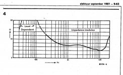
1) First image below shows the oldest measurement that I know of from the magazine Elektor in 1981, unfortunately this graph stops at 20Khz, making it not 100% clear whether this becomes a peak or not.
2) Second image shows the impedance curve of the current LTSpice model.
This one definitely has no peak at 20Khz, but it resembles the Elektor image to some degree.
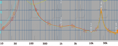
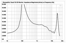
3) Third image is from the ESL 63 measured by Stereophile
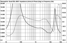
4) Fourth Image is taken from the 2805 measured by Stereophile
5) And fifth image is recently measured by 1Audio from an ESL63.
What can be seen is that:
A) all measurements are peaking at ca 20Khz, but not the LTSpice model.
B) the LF peak various quite a bit between all images in frequency and Q.
Most have their peak between 50 and 70Hz, but the ESL63 measurement from Stereophile has a much smaler peak at 110Hz.
C) Only 1Audio's mesurements extend beyond 50Khz, where impedance is around 4 Ohm and still going down, where the impedance of the Sim model is already 14 Ohm@50Khz and ramping up because of the leakage inductance of the transformer.
So what can we learn from this, is it the Audio transformer that has a very large spread, or are different transformers used from time to time ?
And why do the all measurements have this impedance peak at 20Khz, except for the LTSpice model that doesn't have this peak ?
I think the Audio transformer and/or the delay line inductor are still keeping a few secrets. Would be nice if we could do some more measurements on these parts.
Hans
After having managed to get a satisfactory LTSpice model for FR and impulse response, one thing still puzzles me and that's the impedance.
Below a series of various impedance curves, images are normalised from 0 to 20 Ohm and from 10hz to 50Khz, but all being quite different:
1) First image below shows the oldest measurement that I know of from the magazine Elektor in 1981, unfortunately this graph stops at 20Khz, making it not 100% clear whether this becomes a peak or not.
2) Second image shows the impedance curve of the current LTSpice model.
This one definitely has no peak at 20Khz, but it resembles the Elektor image to some degree.
3) Third image is from the ESL 63 measured by Stereophile
4) Fourth Image is taken from the 2805 measured by Stereophile
5) And fifth image is recently measured by 1Audio from an ESL63.
What can be seen is that:
A) all measurements are peaking at ca 20Khz, but not the LTSpice model.
B) the LF peak various quite a bit between all images in frequency and Q.
Most have their peak between 50 and 70Hz, but the ESL63 measurement from Stereophile has a much smaler peak at 110Hz.
C) Only 1Audio's mesurements extend beyond 50Khz, where impedance is around 4 Ohm and still going down, where the impedance of the Sim model is already 14 Ohm@50Khz and ramping up because of the leakage inductance of the transformer.
So what can we learn from this, is it the Audio transformer that has a very large spread, or are different transformers used from time to time ?
And why do the all measurements have this impedance peak at 20Khz, except for the LTSpice model that doesn't have this peak ?
I think the Audio transformer and/or the delay line inductor are still keeping a few secrets. Would be nice if we could do some more measurements on these parts.
Hans
Attachments

Hi Hans,
I will try to scan an test from the old Danish High-Fidelity where there are test data. I will send it to you shortly.
I know Danish is not easy to read. Hopefully you can make some sense of the measurements.
Mogens
I will try to scan an test from the old Danish High-Fidelity where there are test data. I will send it to you shortly.
I know Danish is not easy to read. Hopefully you can make some sense of the measurements.
Mogens
Hej Hans,
Let me know if there is any trouble seeing the files. There is some plots with impedance there might be of interest to you. Let me know if there is a few things you need translated.
quad-esl63.zip - Google Drive
Cheers,
Mogens
Let me know if there is any trouble seeing the files. There is some plots with impedance there might be of interest to you. Let me know if there is a few things you need translated.
quad-esl63.zip - Google Drive
Cheers,
Mogens
Hi Mogens,Hej Hans,
Let me know if there is any trouble seeing the files. There is some plots with impedance there might be of interest to you. Let me know if there is a few things you need translated.
quad-esl63.zip - Google Drive
Cheers,
Mogens
thanks a lot for sending this article.
You are right, Danish is a very difficult language for me to understand, almost Chinese. 😀
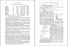
I have tried to translate the text belonging to the three most interesting pictures, attached below.
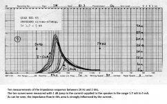
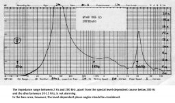
Especially interesting is the Impedance curve for very low currents, haven't seen this before.
But here again is the 15 Ohm peak slightly above 20 Khz in the second image.
Also very interesting is to see the impedance curve from 30 KHz to 200 kHz, again lifting a part of the veil, most likely indicating that the leakage inductance has a Cpar of 35pF in combination with a Rser.
The Audio transformer is a hard nut to crack if you don't have the real thing lie in front of you.
Hans
Attachments
Last edited:
Hi Hans,
Your welcome. It always nice to see a kindred spirit of these loudspeakers. Despite all their faults I have a very soft spot for them besides I think they sound great.
IMG_20180521_133129.jpg - Google Drive
I'm still in the process of re-building my house but hopefully I will get to the point where I can install them in my music-room. Might have hunt Sheldon in case I need to do some repairs. 😀
Speaking of Sheldon. Perhaps he has a spare transformer he could measure. I would be glad to measure one of mine if everything else fails. It's just my workshop is filled with boxes while rebuilding the house. So it will take a little bit of work to get to the speakers. But, at least I can see where they are 😀
Sorry for drifting a bit off-topic. While being slight off-topic I have the schematics for the Gradient SW-63 if anyone is interested and some pictures of the board.
Let's see if Sheldon steps in. Else I will have to dig out a speaker.
Cheers,
Mogens
Hi Mogens,Hi Hans,
Let's see if Sheldon steps in. Else I will have to dig out a speaker.
Cheers,
Mogens
Thanks again and success with your house.
Hans
- Home
- Loudspeakers
- Planars & Exotics
- QUAD 63 (and later) Delay Line Inductors