Hi Lynn, could you clear up my confusion re/ LTV-817B (in the BOM) vs the LTV-827B (in the latest schematics)?
You seem to have changed this on the schematics, together with the value of R16, which was 22K/.5W, and is now 47K/.5W
It looks to me that LTV-827B is just the dual-optocoupler version (and thus would not fit the PCB), so I guess that should just be re-labled in the schematics.
But why the change of R16 to 47K? Thanks!
You are correct about the part numbers on the optocouplers. They should be LTV-817B 1-channel optos. In the original prototype I was using 2-channel optos, but eliminated the one associated with the SIT drain. The A,B,C,D designations are for the CTR (current transfer ratio) group.
R16: The simulations and the actual prototype build differ here. Use the value in the BOM which should be 22K/.5W. Increasing R16 increases the bias current.
Small "bug" in the OS BOM:
the P4 and P5 trimmers specified are the "Y" version:
P4 5K Bourns top-slot trimmer 652-3386Y-1-502LF (pins 1&3 reversed vs. 3386P)
P5 20K Bourns top-slot trimmer 652-3386Y-1-203LF (pins 1&3 reversed vs. 3386P)
Unfortunately these don't have the right pin layout and won't fit on the PCB.
I'm afraid we do have to use the P versions (mouser 652-3386P-1-502LF and 652-3386P-1-203LF).
When I did the PCB layouts I got the front/back convention of the Bourns pin conventions backwards. Their datasheets give bottom views of the pin layouts, rather than top views.
The options are:
- Use the P versions and have the CW/CCW adjustment backwards from what I intended, i.e. CW would decrease bias or voltage.
- Use the Y versions and place a 0.1" kink in the wiper-lead to make it fit the hole pattern.
Unlike many of the diyAudio PassLabs forum construction projects, the SIT3X has many parameters that can be tuned.
- 2SK182ES SIT operating point
- Vds: Adjusted by P4. Limited by rail voltages and desired maximum voltage swing.
- Bias current: Adjusted by P5. Limited by heatsink capacity.
- PFET modulation ratio (Schade feedback): Adjusted by P6. Has major effects on harmonics and output behavior.
In case you wanted to order nylon shoulder washers to insulate the mounting screws for the SIT from Mouser (Lynn had a DigiKey number RPC6397-ND), I ordered the 144-MNI-8-8, which seem to work.
I also ordered the 644-E18-8RB-Q ring terminal for the SIT source wire. They work with M4 (for the pFET) and #6 screws that I'll use for the SIT, but don't quite fit the MNI-8-8 nylon washer -- I also ordered 144-MNI-6-6, which have the right size for going through the ring terminal.
Just in case you want an all-Mouser order.
I'm making slow progress here.
In case you wanted to order nylon shoulder washers to insulate the mounting screws for the SIT from Mouser (Lynn had a DigiKey number RPC6397-ND), I ordered the 144-MNI-8-8, which seem to work.
I also ordered the 644-E18-8RB-Q ring terminal for the SIT source wire. They work with M4 (for the pFET) and #6 screws that I'll use for the SIT, but don't quite fit the MNI-8-8 nylon washer -- I also ordered 144-MNI-6-6, which have the right size for going through the ring terminal.
Just in case you want an all-Mouser order.
I'm making slow progress here.
Thank you: Good info. I will add that to the BOM.
The shoulder washers look to be a very tight. I measured the 2SK182ES mtg. hole diameters right at 0.205", which is the exactly the same as the outer diameter of the 144-MNI-8-8. Same with the ring terminal.
You can get by with only 10mF 16V caps for C5. My original SIT3X prototype used only 2X 4.7mF 16V caps for C5 and it measures and sounds fine.In the version with Cap.Multiplier capacitor C5 is 3 x10 mF x16V.
Can I use only one RIFA169 10mF x16 in this case?
Or is it better to be 30 mF x16?
Thank you.
However, I am not sure how you would mount the RIFA screw terminal capacitor to the PCB.
Thanks a lot for the answer.
I don't think I need to put it on the PCB. Let it get close to the PCB OS and connect the RIFA (-) and IXTN40P50 (S) with a short cable with two M5 O-rings at the end.But I think I will do at the beginning as in your version, after which I will experiment")
I don't think I need to put it on the PCB. Let it get close to the PCB OS and connect the RIFA (-) and IXTN40P50 (S) with a short cable with two M5 O-rings at the end.But I think I will do at the beginning as in your version, after which I will experiment
STOCK: C8188 C8187 Crown Gold Sealed Transistor TO-3 BUZ905D BUZ900D BUZ900 BUZ905 2sk76 2SJ26 2SK60 2SJ18 Budweiser tube 70473180 70483180 70484200 70474200 D8274-9 MOT ON ........
LM350K LM338K LM150K NSC OPA111BM BB 2SK182ES 2SK180 THF-51N MJ21193 MJ21194 MJ21195 2SK1058 2SJ162 2SK1530 2SJ201 2N5566 2SB206 2SB205 2SB555 2SD600 MJ15025 MJ15024 MJ15023 MJ11016 MJ11015 MJ11032 MJ11033 2SK1522 2SA1943 2SC5200 2SB555 2SC1195 2SD424 2SB554 2SC1116 2SA747 2SA745 2SA908 2SA909 2SD166 2SD188 2SD180 2SC1871A BUX48A BUX98A 2SC2246 2SD297 2SC1431A ......
Various models are complete, you need to contact email: 378632242@qq.com
STOCK: C8188 C8187 Crown Gold Sealed Transistor TO-3 BUZ905D BUZ900D BUZ900 BUZ905 2sk76 2SJ26 2SK60 2SJ18 Budweiser tube 70473180 70483180 70484200 70474200 D8274-9 MOT ON ........
LM350K LM338K LM150K NSC OPA111BM BB 2SK182ES 2SK180 THF-51N MJ21193 MJ21194 MJ21195 2SK1058 2SJ162 2SK1530 2SJ201 2N5566 2SB206 2SB205 2SB555 2SD600 MJ15025 MJ15024 MJ15023 MJ11016 MJ11015 MJ11032 MJ11033 2SK1522 2SA1943 2SC5200 2SB555 2SC1195 2SD424 2SB554 2SC1116 2SA747 2SA745 2SA908 2SA909 2SD166 2SD188 2SD180 2SC1871A BUX48A BUX98A 2SC2246 2SD297 2SC1431A ...... TO-92 TO-247 TO-3 TO-220 TO-3P SOP DIP CDIP SMD
Various models are complete, you need to contact email: 378632242@qq.com
Note to SIT3X builders:
A dirty secret: I found that some tuning of the IDSS the input JFETs was useful to obtain better H2/H3 values with negative H2 relative phase. The IDSS values I have used with similar results were:
socket strips.
Depending on your 2SK182ES characteristics, each channel will require some tuning of JFETs and the P6 "magic" X-pot.
A dirty secret: I found that some tuning of the IDSS the input JFETs was useful to obtain better H2/H3 values with negative H2 relative phase. The IDSS values I have used with similar results were:
- J74 7.3mA paired with K170 4.7mA
- J74 11.1mA paired with K170 7.8mA
socket strips.
Depending on your 2SK182ES characteristics, each channel will require some tuning of JFETs and the P6 "magic" X-pot.
Sorry, but I under estimated the number of people who would want boards. There might be another batch of boards build after I get feedback about the current boards and make any necessary design changes.Ihquam Are there any boards left?
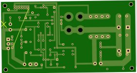
tbald53892, the first fearless SIT3X builder, has discovered an artwork error of the Right-OS PCB. The image below shows what must be done to correct the error. On the back side of the PCB:
- Cut one trace.
- Add one jumper wire.
Attachments
- Home
- Amplifiers
- Pass Labs
- The SIT-3X Amplifier