I have been participating in the effort, led by 2 picoDumbs, to make a 4U, 500mm deep chassis available for the diyAudio community. We have made some good progress, including a new pre-order offering that is now in the store. As described by Jason in Ultimate 4U 500mm Chassis - Who is interested?, this will include UMS compatible heatsinks and the option for deluxe style front and rear plates, as well as the perforated inner bottom plate.
We also continue to work on a spec for a somewhat more custom chassis that will have the same dimensions, but a different configuration for the top and bottom plates, plus different options for the front and rear plates. This will likely be a smaller group buy once we can finish the details.
These chassis should handle the single transformer / single rail SIT-3X configuration adequately regarding power dissipation. They also provide sufficient room for a pair of Antek 500VA or 600VA transformers, although power dissipation capacity may need to be augmented a bit depending on the rail voltages. As far as physical size and weight are concerned, this is probably the maximum I'm willing to haul between my kitchen island workshop and the living room listening space. No stairs involved, fortunately.
Given the latest information about the correction to the grounding scheme and equal viability between the single or dual transformer power supplies, I now have another choice to make.
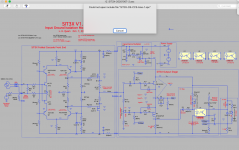
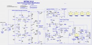
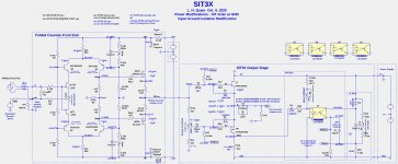
Attached is a zip file containing the LTSpice files for simulating the two major versions of the SIT3X amplifier. Unzip the files into a directory and you should be able to run LTSpice on the .asc files. The file SIT3X-waves.spc contains parameter definitions for the transient response simulation. The file models.spc contains transistor models and a few other models.
I believe that the file collection is self contained, not depending on other files in my environment. Let me know about problems.
I believe that the file collection is self contained, not depending on other files in my environment. Let me know about problems.
Attachments
I see I am late for the party. Is it possible to get PCBs?
Sorry to say, but I am out of boards. There might be another fabrication run, but it will be a while, and certainly not until there is sufficient feedback on builds using the current boards to know what changes are required.
Lynn - Just about ready to fire this thing up - just a few more little details. It's basically a copy of your original prototype: same schematics/transformer/heatsinks/fans etc. I know there have been a few mods (0R47 ground resistor, TIP31C and TIP32C replacements, different output caps, and perhaps a few more I've missed!) but I'm thinking I'll get to these after I confirm the amp is running ok. I have checked the all the power supplies using dummy loads and all is well. So you have mentioned creating a power up recommendations document - well, I'll probably be ready when you are! Many thanks!
Sorry to say, but I am out of boards. There might be another fabrication run, but it will be a while, and certainly not until there is sufficient feedback on builds using the current boards to know what changes are required.
Oh, there is no rush. Count me in for next round
Lynn - Just about ready to fire this thing up - just a few more little details.
...
So you have mentioned creating a power up recommendations document - well, I'll probably be ready when you are! Many thanks!
Attached is a pdf file describing the adjustment procedure. Give me feedback to improve the document.
Attachments
Request to all builders: I need suggestions on how to present the information you need for your builds. There appear to be three variants of the SIT3X:
Give me suggestions about the best way to present the information that you need.
- Fan cooled prototype with +/-44V rails, capacitance multiplier, ...
- 5U 400mm chassis with +/-34V rails, capacitance multiplier, ...
- 5U 400mm chassis with 0V/-88V, NO capacitance multiplier, ...
Give me suggestions about the best way to present the information that you need.
Lynn - In the Initial Adjustments document, FCFE Adjustment section, second para, I believe the reference to R35a(b) should be R35b/R36b. Thanks!
It seems I will be blazing my own trail somewhat with this build. Not uncommon for me.
Since I prefer a finished chassis that is not too heavy to carry, I'm working on a small group build of a 4U, 500mm chassis which will have a custom variation on the UMS hole pattern in the heatsinks, as well as some sort of pre-drilled backplate and perforated top and bottom plates. The UMS hole pattern won't be used by the SIT-3X boards, but is a nice option to have for other amps. The most likely supply configuration for my SIT-3X will be +/– 34V rails w/ capacitance multiplier.
It will be some time before we get these chassis made, so I won't be able to offer feedback on initial adjustments and power dissipation until later.

Hi Lynn, could you clear up my confusion re/ LTV-817B (in the BOM) vs the LTV-827B (in the latest schematics)?
You seem to have changed this on the schematics, together with the value of R16, which was 22K/.5W, and is now 47K/.5W
It looks to me that LTV-827B is just the dual-optocoupler version (and thus would not fit the PCB), so I guess that should just be re-labled in the schematics.
But why the change of R16 to 47K? Thanks!
Small "bug" in the OS BOM:
the P4 and P5 trimmers specified are the "Y" version:
P4 5K Bourns top-slot trimmer 652-3386Y-1-502LF (pins 1&3 reversed vs. 3386P)
P5 20K Bourns top-slot trimmer 652-3386Y-1-203LF (pins 1&3 reversed vs. 3386P)
Unfortunately these don't have the right pin layout and won't fit on the PCB.
I'm afraid we do have to use the P versions (mouser 652-3386P-1-502LF and 652-3386P-1-203LF).
- Home
- Amplifiers
- Pass Labs
- The SIT-3X Amplifier