
In the FCFE scheme R37a and R37b have the value of 10K.
In BOM they are indicated as 24K.
How is it correct?
For R37a/b, use 10K 1/2W resistors:
R37a/b 10k 603-MFR50SFTE52-10K 1/2W
The change was made to obtain sufficient current through the TL431 for proper operation at lower rail voltages.
tbald53892 has been "debugging" his build and discovered one or more problems in the FCFE TL431 circuits. We are still working to resolve the issue. Hold off for a while on ordering parts. There might be changes to the pot values and the two resistors.
Could it be the same problem that some were having with the F4 amp, not enough current for the tl431 to activate? Using 10k ohms might fix it. TLVH431 is a low current version.
The change was made to obtain sufficient current through the TL431 for proper operation at lower rail voltages.
Opps, I did not see this sentence, never mind.
The TLVH431 might be a good idea because of the low KA voltage. The datasheets show that the phase margin improved greatly with increased V(KA). I am seeing noise, probably due to oscillation, with some TL431 devices with only about 4 volts from cathode to anode.Could it be the same problem that some were having with the F4 amp, not enough current for the tl431 to activate? Using 10k ohms might fix it. TLVH431 is a low current version.
Are there and decent Spice models for the TLVH431
Are there and decent Spice models for the TLVH431
I found this TLVH431 model.
Attachments
I am not convinced that either switching to the TLVH431 voltage regulator or adding capacitors to the TL431 circuits in the FCFE will provide a bulletproof solution to the broadband noise problem that both tbald53892 and I have seen. I am considering a circuit change using a zener rather than the TL431, which also requires adding a capacitor.
Both approaches will have some noise. I think an RC network is what will
be needed. Also, you will want to consider balancing the resistance to the
bases of these cascodes, making an RCR something to explore.
be needed. Also, you will want to consider balancing the resistance to the
bases of these cascodes, making an RCR something to explore.
The "broadband noise" I described might be due to some kind of oscillation rather than typical thermal noise. With two FCFE PCBs stuffed with parts from the same batches, the 1st of the boards had measured noise levels in the vicinity of 0.1mVrms-0.2mVrms and the 2nd board had noise in the vicinity of 1mV. The sound of the 2nd board was that of broadband noise. Spectrum plots confirmed the Vrms measurements, showing virtually no 60Hz harmonics.
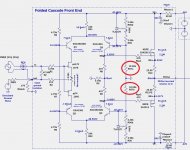
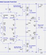
The broadband noise problem was "fixed" by adding capacitors between the TL431 ref and cathode pins as shown in the first image below. However, I have not found an satisfactory justification for this solution. Adding capacitors between the TL431 cathode and anode pins did not fix the problem as is recommended in the Texas Instrument Application Report SLVA482A – September 2011 https://www.ti.com/lit/an/slva482a/slva482a.pdf.
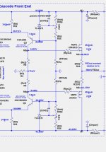
The 2nd image below shows the zener diode alternative I am considering. It does contain an RC network formed by the resistor-pot-resistor network and the electrolytic capacitor. This circuit has not yet been bench tested.
The broadband noise problem was "fixed" by adding capacitors between the TL431 ref and cathode pins as shown in the first image below. However, I have not found an satisfactory justification for this solution. Adding capacitors between the TL431 cathode and anode pins did not fix the problem as is recommended in the Texas Instrument Application Report SLVA482A – September 2011 https://www.ti.com/lit/an/slva482a/slva482a.pdf.
The 2nd image below shows the zener diode alternative I am considering. It does contain an RC network formed by the resistor-pot-resistor network and the electrolytic capacitor. This circuit has not yet been bench tested.
Attachments
You could also consider an LM329 in place of the 6.8V zeners. It has a very low temperature coefficient.
This bias circuit is used to control the bias current to the FE output FETS (2SJ313/2SK2013). Given all of the other components (JFETs, BJTs, MOSFETs) with temperature sensitivities, I do not think the zener (or TL321) temperature stability to be the major contributor.You could also consider an LM329 in place of the 6.8V zeners. It has a very low temperature coefficient.
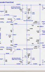
I finally tested the FCFE zener modification today which eliminates the TL431s, and everything checks out. Shown below are the mods I made.
- With the FCFE input shorted, the OS out RMS noise is unmeasureable on Fluke meter whose sensitivity is 0.1mV.
- I cannot hear any noise with my ear against the speaker cone.
- The spectrum is very clean, with only a bump at 60Hz and no other harmonics of 60Hz are measurable.
Attachments
One issue I am facing with the SIT3X is that the harmonic structure is defined by the 2SK182ES, the operating point (Vds, Id), and the magic X pot setting. From the small signal equations of the output stage, I have found some interesting results that have similarities to those for the SIT mu-follower, which I discussed in SIT measurements, Mu Follower, and amplifier build.
The bottom line is as follows:
My SIT3X is running (mostly) the latest circuit modifications and sounds very good, but might be a little starved of H2, the 2nd harmonic. Should I deliberately create more H2 in the FCFE? The (optional) pot on the FCFE JFET source pins can alter H2, as can choice of JFETs.
The bottom line is as follows:
- The FCFE has such low distortion that it has little contribution to the overall harmonic structure.
- The X-pot changes the relative contribution of the SIT and the PFET to the output signal.
- similar to the "gain-factor" of the mu-follower
- changes RL, the "effective load" seen by the SIT, which defines the slope of the load line.
- The SIT Id and Vds at idle state change the position of the load line.
- All of the above change the 2nd harmonic.
My SIT3X is running (mostly) the latest circuit modifications and sounds very good, but might be a little starved of H2, the 2nd harmonic. Should I deliberately create more H2 in the FCFE? The (optional) pot on the FCFE JFET source pins can alter H2, as can choice of JFETs.
I do not understand the change you suggest. R3 will certainly change the gain of the FCFE, but has little affect on the harmonic structure..... and I believe value of R3 can make some changes
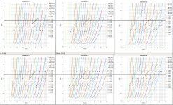
Here is a mind blowing presentation of measurements made of six different 2SK182ES SITs.
Two types of measurements are shown in the plots:
The horizontal black lines at 1.8A are my choice of Id in the SIT operating point. The diagonal black lines assume That I have adjusted my X-pots such that the PFET acts as a CCS, and RL=Rload=8Ohms. In each plot you can find the necessary Vds value where the RL=8R line crosses 1.8A.
Two types of measurements are shown in the plots:
- The FrankenTracer circuit was used to measure the Id vs Vds for constant values of Vgs, shown as solid curves whose colors are in the legend of the right.
- The SITs were operated common-source with a constant current source load, measuring spectra at different operating points Vds and Id, and different resistive loads RL. For given values of Id and RL, values of Vds were found where H2 was minimized. The dotted curves of constant RL show the H2 null lines whose colors are in the legend of the right.
The horizontal black lines at 1.8A are my choice of Id in the SIT operating point. The diagonal black lines assume That I have adjusted my X-pots such that the PFET acts as a CCS, and RL=Rload=8Ohms. In each plot you can find the necessary Vds value where the RL=8R line crosses 1.8A.
Attachments
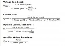
All right ZM -- you asked for it -- equations! 😱
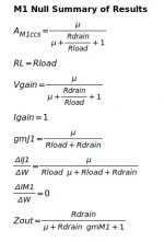
The right image is the for A which results in M1 acting as a CCS for a specific Rload.
- μ and Rdrain are the Triode parameters of the SIT.
- gmM1 is the transconductance of the PFET.
- A is the magic X-pot value.
The right image is the for A which results in M1 acting as a CCS for a specific Rload.
Attachments
I tried some different R3 values in the 2:1 range and H2/H3 can be made to increase with higher values of H3. However that increases the gain of the front end.try it in sim, it's 5min
I'm not sure how much, just an idea
If I also change R4 by the same factor, there is no significant change in H1, H2, or H3. That test was over a range from 1X to 4X the original R3 and R4 values.
- Home
- Amplifiers
- Pass Labs
- The SIT-3X Amplifier