I did more bench tests with the SIT3X prototype today, working on the FCFE PSRR anomalies.
I restored the prototype FCFE boards to use the original 2 stages of filtering and the FCFE output 60Hz harmonics essentially vanished when the inputs are grounded with no connection between the left and right input grounds.
When the input grounds are connected, the 60Hz harmonics rise by about 20dB, raising the OS output noise level to around 1mV.
I experimented with different ground paths and connection topologies for the RCA inputs and found that by moving wires around in different ways the harmonics would change considerably.
CONCLUSION: I think that the physical separation of the FCFE JFET inputs from one another in the power transformer fields causes this problem, and can be addressed as follows:
- FirstWatt way: front-ends on separate boards with input JFETs as near as possible to the RCA inputs and as far away as possible from the transformer.
- PassLabs way: front-ends on a single board with common grounding and JFETs close to RCA inputs.
Any PCB purchasers who have not received their boards yet should send me a PM. It might require another fabrication run, which will include some upgrades to the design. Some who have received boards, have not begun to build, and are not in a hurry to build could sign up for the revised PCBs.
Power Supply Ground Issue Resolved -- Finally:
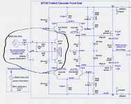
I found a very simple change to the FCFE JFET input that fixes the problem due to transformer fields affecting the wiring paths between the power supply(s) and the FCFE PCBs. Due to the 10X voltage gain of the FCFE, it requires only about 100uV of difference in the induced transformer noise to the FCFE signal grounds to create 1mV noise at the output.
The 1st image shows the circuit modification placing a 0R47 resistor between the RCA ground and the FCFE signal ground, and to tying the ground end of R4 to the RCA ground.
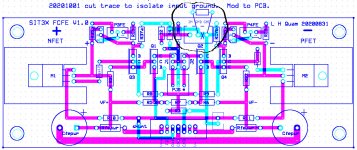
The 2nd image shows the change to the FCFE V1.0 PCBs, cutting one trace and adding one 0R47 resistor between the two ground pins on the input terminal block. The reason that this works is because the JFET input circuit is a differential amplifier with inputs at the gates and the source pins, and can tolerate a common mode signal on the those inputs. In this case, the common mode signal is the difference between the RCA ground and the FCFE signal ground.
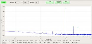
The 3rd image below shows the Output spectrum for 1 Watt into 8R. You can see that the 60Hz harmonics are 94dB or more below the 1 Watt level, or 2.82/10^(94/20)=58uV, and the broadband noise spectrum is very good.
I found a very simple change to the FCFE JFET input that fixes the problem due to transformer fields affecting the wiring paths between the power supply(s) and the FCFE PCBs. Due to the 10X voltage gain of the FCFE, it requires only about 100uV of difference in the induced transformer noise to the FCFE signal grounds to create 1mV noise at the output.
The 1st image shows the circuit modification placing a 0R47 resistor between the RCA ground and the FCFE signal ground, and to tying the ground end of R4 to the RCA ground.
The 2nd image shows the change to the FCFE V1.0 PCBs, cutting one trace and adding one 0R47 resistor between the two ground pins on the input terminal block. The reason that this works is because the JFET input circuit is a differential amplifier with inputs at the gates and the source pins, and can tolerate a common mode signal on the those inputs. In this case, the common mode signal is the difference between the RCA ground and the FCFE signal ground.
The 3rd image below shows the Output spectrum for 1 Watt into 8R. You can see that the 60Hz harmonics are 94dB or more below the 1 Watt level, or 2.82/10^(94/20)=58uV, and the broadband noise spectrum is very good.
Attachments
Hi Lynn, I have a quick question regarding the output caps: in the new power scheme, doesn't C5 now have to hold DC of typically 35V, and (for a sine at 50 Watts into 8 Ohms => Upeak = 28.3V) theoretically even 64V?
The BOM still has the 16V Nichikons, I'm wondering if we need to replace those with the 50V or even the 63V version (like LKG1J103MKN ?), to be safe?
Or does it not matter much (although, exploding caps could be unpleasant)?
Thanks, LatB
The BOM still has the 16V Nichikons, I'm wondering if we need to replace those with the 50V or even the 63V version (like LKG1J103MKN ?), to be safe?
Or does it not matter much (although, exploding caps could be unpleasant)?
Thanks, LatB
Hi Lynn, I have a quick question regarding the output caps: in the new power scheme, doesn't C5 now have to hold DC of typically 35V, and (for a sine at 50 Watts into 8 Ohms => Upeak = 28.3V) theoretically even 64V?
The BOM still has the 16V Nichikons, I'm wondering if we need to replace those with the 50V or even the 63V version (like LKG1J103MKN ?), to be safe?
Or does it not matter much (although, exploding caps could be unpleasant)?
Thanks, LatB
You are correct. I just received a set of 6.8mF 50V "audio grade" electrolytic caps for that reason. Mouser #647-UKW1H682MRD. Two caps per OS board. It might be nice to use 20mm diam. 50V caps with capacitance greater than 4.5mF.
I will check again, but I thought I created a BOM for the new OS power arrangement.
Last edited:
seems it's not yet on GitHub. I'm assuming C3 and C4 also will have to be 50V, like 667-ECE-A1HN221UB? C7 can stay at 25V?
seems it's not yet on GitHub. I'm assuming C3 and C4 also will have to be 50V, like 667-ECE-A1HN221UB? C7 can stay at 25V?
Correct. C7 can be even lower voltage since it only sees the difference between the gate voltages of J1 and M1.
Hopefully, I will find some time tomorrow to update the HTML files at github.
In post #603 I reported changes to the FCFE input grounding and bench test noise measurements. I moved the SIT3X from my workshop upstairs to my listening room. Both channels of the amplifier are now dead quiet with the ear at the speaker. No hum and no broadband noise. This is with a power supply using a single transformer having only two secondaries.
Success at last!
Success at last!
Congratulations! Once again, thank you for your dedication and sharing your process of examining the performance and troubleshooting. I'm learning a bit as I go along.
Thank you for the support. When I get some time I will put together a document describing some of these issues in more detail.
My thanks go out to generg (Gerd Bethge) for encouraging me to pursue amplifiers using SITs by donating some 2SK182ES SITs to me. A long chain of simulation and bench tests lead me to the SIT3X design.
My thanks go out to generg (Gerd Bethge) for encouraging me to pursue amplifiers using SITs by donating some 2SK182ES SITs to me. A long chain of simulation and bench tests lead me to the SIT3X design.
To the SIT3X board buyers: There is really no reason to defer your builds, waiting for the a fabrication run of revised PCBs. All modifications to the V1.0 boards are trivial: a trace cut or a jumper. The only reason for a possible new fab run is for additional builders and previous buyers whose shipments didn't get to them.
If you make final changes, I will be happy to add my name to a list to get final boards. I can place an order if you want help with logistics. I have some SIT parts waiting for a build.
Your work is outstanding. Congrats on a super exiting design.
Your work is outstanding. Congrats on a super exiting design.
Power Supply Ground Issue Resolved -- Finally:
Congratulations and a big thank you also from here -- I'm really excited following your project. My 2SK182ESs just arrived from Japan, after 2.5 months in transit (thank you Tomoaki Watanabe!). I also have the Hockey Pucks, but am just starting to put together the Mouser order for the OS.
Would you mind including the spice simulation models you're using for the SITs etc on GitHub, or maybe just a pointer to where one could find them? I'm only starting to use LTspice and that would be very helpful -- but maybe those are "secret"?
I'm still thinking about the power supply options. I'm considering to use +/- 34V rails for the OS instead of the single-rail option. I'll still have a separate +/- 44V PSU for the FCFE, possibly the Salas SSLV1.3 UltraBiB shunt supply -- although that might be overkill. Initially I might just use a BA-3 gain stage, to get going -- do you think that could work as an interim or is this OS just too hard to drive?
Just two questions. I have received the boards from Lynn:-
Are the output capacitors necessary, even when I configure the Output Stage with Dual Polarity rails? Or are they necessary only with -68/Gnd rails?
Any feedback on the sonic qualities of the two configurations? Thanks.
Are the output capacitors necessary, even when I configure the Output Stage with Dual Polarity rails? Or are they necessary only with -68/Gnd rails?
Any feedback on the sonic qualities of the two configurations? Thanks.
There are several reasons that the output capacitors are necessary for both power supply configurations:
- Without any DC feedback or servo, the idle voltage of the SIT/PFET source node will not be sufficiently stable.
- Within limits imposed by the rail voltages and the desired maximum output voltage swing, the SIT Vds can be adjusted to a different point on its load line to change the sonic character, mostly H2.
The SIT3X might be my last big amplifier, since it weighs in excessive of 50# and carrying it up and down stairs between my shop and my listening area is getting more difficult with age. The solution will have to be either smaller stereo amps or monoblocks.
The SIT3X might be my last big amplifier, since it weighs in excessive of 50# and carrying it up and down stairs between my shop and my listening area is getting more difficult with age. The solution will have to be either smaller stereo amps or monoblocks.
When I build mono blocks, I use the same chassis as a stereo amp, tend to up size the power supply, also more heat sinking and the bottom line is the limit is the same 50 pound weight anyway.
They probably sound better as mono blocks, but I am hampered by funding and space. I have 5 stereo amps, using only one at a time. Could not house 10 chassis and look, planning to build yet another one.
What is wrong with me?
A sickness I guess.
Rush
Lynn, thanks for replying elaborately. Monoblocks is the way, I am thinking of for my SIT-3X.
Since I don't usually have mammoth supply caps, but have always used Cap multipliers for Class A amp builds with 10,000uF - 15,000uF, caps before and after cap multiplier, I was thinking, what if I use the same scheme for the single supply SIT-3X, leaving out centre zero? Will this be better than having a single cap multiplier in only the minus rail?
Since I don't usually have mammoth supply caps, but have always used Cap multipliers for Class A amp builds with 10,000uF - 15,000uF, caps before and after cap multiplier, I was thinking, what if I use the same scheme for the single supply SIT-3X, leaving out centre zero? Will this be better than having a single cap multiplier in only the minus rail?
Last edited:
For the SIT3X Builders: Based on post #603, it appears that either the single transformer or dual transformer power supplies should have essentially the same output noise spectra. I plan to do a build using a stripped Sonnance amplifier chassis using a single transformer and the 2-channel caps board.
- Home
- Amplifiers
- Pass Labs
- The SIT-3X Amplifier