I am working on producing a document (html and/or pdf) that will tie together much of the documentation, including the design history. The BOM info will remain as it is.
For now use the information in the github repository GitHub - lhquam/SIT3X-Power-Amplifier.
For now use the information in the github repository GitHub - lhquam/SIT3X-Power-Amplifier.
Need ixtn40p50p friends, you can find me, I have stock, pcdb circuit board inside some of the small electronic components, I can give free
There is now an HTML file tree for the SIT3X in the git repository. I suggest you delete any previous downloads from GitHub - lhquam/SIT3X-Power-Amplifier and download and unzip the new contents.
In your browser you can view the file SIT3X-Power-Amplifier.html in the unzipped directory. There are hotlinks to additional HTML files of the tree. All of the previous files should still be there too.
There are more sections to be added:
In your browser you can view the file SIT3X-Power-Amplifier.html in the unzipped directory. There are hotlinks to additional HTML files of the tree. All of the previous files should still be there too.
There are more sections to be added:
- measurements of the prototype
- instructions for initial power-up (smoke testing)
- adjustment
I am not sure I understand what you mean by "Ids with a given load". Wouldn't Vp and Ids depend on Vds also because on the triode behavior of the device?
Have you found that by selecting using those parameters that other device characteristics tend to "correlate".
1) Yes, of course, but we are talking about practical matches between
devices with the same part number.
2) Yes, pretty much, again assuming same part # (or if you wish to be
fussier yet, within a lot code).

For all of the SIT3X builders: hold off on ordering power transformers. I think Rush and I have found a good way to reduce the transformer secondary voltage without sacrificing output power. This will allow higher power operation when using the 5U 400mm chassis or other heatsink limited chassis.
I will expand on this note soon.
I will expand on this note soon.
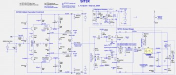
Here is the situation. The rail voltages for the SIT3X prototype were largely determined by my goal for 50W output power into an 8R load (28.28V peak). With fan cooled heatsinks, the idle power dissipated was not an issue. There are two primary factors that necessitate that the rail voltages be more than about 38V to accomplish the 50W goal:
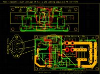
I show below the modified schematic and PCB modifications for such a change.
The major downsides to such a change are:
- The FCFE output voltage swing is about 8 volts less than the rail voltages due to Vgs drops on the Toshiba output FETs, source resistors, and the folded cascode resistors connected to the rails. The voltage swing is further reduced if IRF or Fairchild FETs are used.
- The capacitance multiplier reduces the OS stage maximum output swing by about 5 volts, but that reduction is below the OS rail voltages, and is not dependent on FCFE output swing.
I show below the modified schematic and PCB modifications for such a change.
The major downsides to such a change are:
- Modifications to PCB are required.
- Additional small power supplies are required.
Attachments
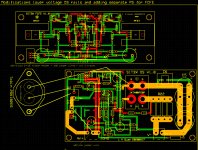
Better yet PCB modification.
- No change to FCFE PCBs.
- On OS PCB
- remove IRFP240 NFET
- drill one hole
- replace 2-position terminal block with 3-position block
- cut one trace as shown
- add 2 jumper wires as shown
Attachments
Last edited:
The SIT (2SK182ES) drain current is sensitive to Vds, because of its triode-like character. Thus it is important that the SIT drain be at a constant voltage relative to the input ground reference. That was the reason for the cap. multiplier when using V+/V- rails rather than 0/V- rails. It you look at the FirstWatt SIT-1 and SIT-2 circuits you will see the use of 0/V- rails.What happens with the noise floor when the cap multiplier is removed?
I have verified the ability to obtain 50W@8R output with THD<1.1% using a transformer with 28Vac secondaries, using a Variac with my prototype. The primary power supply output voltages are +/-34V and the OS bias was 1.8A. I did not disable the cap. multiplier. In order avoid clipping in the FCFE, its power inputs (VFr in the table below) must be +/-42V or higher.
Since I did almost no tuning of adjustable parameters, I expect that it is possible to improve the distortion measurements.
Since I did almost no tuning of adjustable parameters, I expect that it is possible to improve the distortion measurements.
- 1W THD=.018 VFr = 33.9V
- 25W THD=.33 VFr = 33.9V
- 25W THD=.334% VFr = 42.9V
- 50W THD=6.6% VFr = 33.9V
- 50W THD=1.35% VFr = 38.9V
- 50W THD=1.1% VFr = 41.9V
- 50W THD=1.1% VFr = 43.9V
Just about ready to start wiring up my SIT-3X (basically a copy of Lynn's original prototype/transformer/heatsinks/fans). The one outstanding issue is finding the properly sized insulators for the 2SK182ES. Any suggestions as to where I might find such a beast?
Another option:
CD-02-05-C-54 Wakefield-Vette | Mouser Canada
The picture shows a hole but there is no hole, as indicated in its description. I have used this in two of my amps that have Tokin SITs.
CD-02-05-C-54 Wakefield-Vette | Mouser Canada
The picture shows a hole but there is no hole, as indicated in its description. I have used this in two of my amps that have Tokin SITs.
I used insulating thermal paste, something metal-oxide based, no other padding. Works well so far
I used sheet mica and goop. Sheet mica can be hard to find. I think mine came from India.
I have included more construction details for the prototype chassis in the git repository.
I have included more construction details for the prototype chassis in the git repository.
Just about ready to start wiring up my SIT-3X (basically a copy of Lynn's original prototype/transformer/heatsinks/fans). The one outstanding issue is finding the properly sized insulators for the 2SK182ES. Any suggestions as to where I might find such a beast?
- Home
- Amplifiers
- Pass Labs
- The SIT-3X Amplifier