I am planning to totally eliminate the degeneration resistors, making Vgs stability critical.
I am accomplishing gm adjustment by "optimally" attenuating the bias signal to the IXYS puck, and bias current adjustments by adjusting a bias offset between the gates.
I am accomplishing gm adjustment by "optimally" attenuating the bias signal to the IXYS puck, and bias current adjustments by adjusting a bias offset between the gates.
SIT3 Harmonic Cancellation Equations
After stumbling onto the harmonic cancellation as described in post #126 SIT measurements, Mu Follower, and amplifier build, I realized that my previous SIT3 circuit analysis in post #120 SIT measurements, Mu Follower, and amplifier build did not include the possibility of attenuating the signal to the PFET and eliminating its degeneration resistor.
The image below shows the abstract circuit, its circuit equations, solutions, and simplified solutions in terms of four parameters α, β, α_q, and β_q. These equation solutions agree with simulations.
Next step: bench tests using the circuit shown in second image.
Attachments

Just curious, would moving point 'A' to the load be beneficial?
I also looked at equations for that circuit and the behavior certainly allows gm matching, in much the same way as degeneration. Thus far I cannot find circuit parameters that provide harmonic cancellation. In that circuit, the pot changes both the Vgs offset between the FETs and the effective gm of M1, making the parameter search somewhat more complicated.
don't forget Schade tricks, if you want to alter Mosfet's behavior
as seen in my fun with Schade M2 ( my Uncle Bubba Flocchini is one of rare Greedy Boyz who tried it), there is no big price paid in frequency domain, when source follower arrangement is in case
as seen in my fun with Schade M2 ( my Uncle Bubba Flocchini is one of rare Greedy Boyz who tried it), there is no big price paid in frequency domain, when source follower arrangement is in case
After closer examination, the circuit equations for source degeneration of the PFET M1 vs. a resistor divider between Input, M1gate, and M1source are equivalent.Just curious, would moving point 'A' to the load be beneficial?
For both cases, the only situation where harmonic cancellation is possible is when there is no degeneration, the transconductance of the PFET is "optimal" for the SIT operating point. This is because source degeneration inherently introduces harmonics.
With the attenuation of the input signal as shown in post #142, no harmonics are introduced due to degeneration.
Thank you lhquam for the explanation; I suppose on reflection, It would be the inverted ac difference between the IN and S1 that needs to be injected into M1 to cancel the SIT harmonics, but not M1's.... not sure if performing the same trick for M1 could be done without making an oscillator.
There is some magic going on related to the triode nature of the SIT. My equations describe the small signal behavior of the circuits and do not say anything about the harmonic structure, which would require more complete mathematical for the SIT and PFET, making the systems of equations too complicated for direct solution.
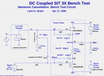
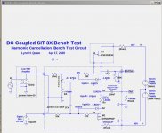
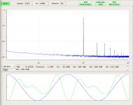
SIT3 harmonic cancellation works:
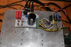
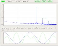
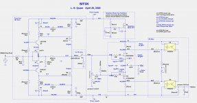
Finally, some bench measurements of the harmonic cancellation. Below are the bench test circuit, a photo of its build, and spectra of the at 1Khz, 1Watt, and Rload=8 and Rload=4. The M1 PFET gate input is adjusted for the "sweet spot". The operating point was:
Finally, some bench measurements of the harmonic cancellation. Below are the bench test circuit, a photo of its build, and spectra of the at 1Khz, 1Watt, and Rload=8 and Rload=4. The M1 PFET gate input is adjusted for the "sweet spot". The operating point was:
- Vds(J1) = 34.5V
- Ibias = 1.8A
Attachments
Last edited:

More SIT3X tests today.
I hooked up my spare ZD25 (similar to XA25) as a low distortion, 10X gain front end. All of the spectra looked very good until I destroyed the IXYS PFET puck, probably due to replugging some cabling and exceeding the SOA of the PFET. My bench test circuit has a definite vulnerability to overcurrent if the DC level of the signal input goes negative. The Tokin SIT seems be be nearly bulletproof in this regard.
The bias current increases with temperature enough that an optocoupler circuit with drain sense resistors is probably needed.
I am convinced that the SIT3X distortion cancellation works as shown in the simulations and it is time to design an appropriate front end. Any suggestions out there? I would like to see 10X gain from a very low distortion FE that can easily drive a 1K (or lower) load.
How about a non-feedback folded cascode FE similar to that in John Curl's Blowtorch, with gets about 0.026% THD at 20V peak output with 6.67X gain. Combined with the SIT3X it would make a totally non-feedback 25W-50W amplifier with very low distortion and excellent damping factor.
Would it work to use the x25 type circuit but put your pot between the drains of the toshiba mosfets with the wiper going to the gate of the IXTK40P50P. The gate of the vfet goes to the drain of the 2SK2013. Except turning the bias adjust pots up at the jfets would turn the puck bias down.
The challenge is to couple this output stage with a suitable non-feedback front-end. Something along the lines of the BA-3 FE, with cascoded JFETs and a gain of 10X looks good. The remaining problems are likely to be bias stability.
By the time the amplifier is complete, it might be very similar to a XA25, with the NFET replaced by the Tokin SIT, feedback removed, FE gain reduced to 10X, bias circuit changed, and a few other things.
By the time the amplifier is complete, it might be very similar to a XA25, with the NFET replaced by the Tokin SIT, feedback removed, FE gain reduced to 10X, bias circuit changed, and a few other things.
Very different in that no feedback loop is needed to obtain very low distortion. What is strange is that the harmonic cancellation adjustment (AC signal level to the gate of the PFET) behaves similarly to the positive current feedback (PCF) adjustment of the F7, where the damping factor can be increased to infinity and beyond to negative damping factors. Since the Tokin SIT and IXYS PFET are not degenerated, the harmonic distortion can be quite low.
I have made considerable progress on a complete design of the 50W/CH Tokin 2SK182ES based source follower amp without and degeneration in the output stage. The front-end still requires feedback in order to provide sufficiently low output impedance to the OS. The specs in the latest design are:
I intend to start a new thread for this amplifier.
- 2SK182 SIT IXTN40P50P PFET
- No feedback around output stage
- adjustable attenuation of signal to PFET gate enables distortion cancellation
- XA25 based FE with feedback from FE out
- Optocoupler bias current control
- Depletion mode capacitance multiplier on SIT drain
- At 1.8A bias current, +/-47V rails
- THD<.01% at 1W
- THD< .1% at 25W
- THD<.25% at 50W
- <100uV PS ripple
- Startup/shutdown "thump" tests look ok
I intend to start a new thread for this amplifier.
Attachments

Last edited:
I have been following your progress with great interest. I am looking forward to the amplifier build thread.
to Ihquam #157
Hello Ihquam,
you did a fantastic job!
I am also thinking for a long time about an input stage (although I built the
IXYS - Mosfet version - no SIT).
My thoughts were:
BA-3 frontend - outputstage with optocoupler- / auto bias between Mosfets
(similar like in WHAMMY headphone-amp) -
very low outputimpedance....
ACP+ as a frontend (longtailed pair with a second stage as MU-follower with auto-bias) Also very low outputimpedance.
And I think if usung one of these two `driverstages`not necessarily a cap between input and outputstage? 🙄
As Nelson Pass said: 'It should have a very low outputimpedance'
My 50W-SE-Schade-amp is very well driven by the B1-Korg-Nutube pre and
the B1 - buffer-preamp.
But to drive the 600 Ohm : 600 Ohm transformer something with 'juice'
would be nice.
Only some thoughts....🙄
Greets
Dirk
- Home
- Amplifiers
- Pass Labs
- SIT measurements, Mu Follower, and amplifier build