when I discovered that funny behavior and wrote about in Most Greedy Boy, of them all... or (there is no) DEFiSIT of Papa's Koans , posts #190,195 etc. , I tried introducing source resistor , measuring and listening (one channel)
I decided that I prefer weirdness of circuit sans any source resistance
🙂
nice to have it covered with math, but I can only , pretty sure that I'll not remember where I did save it, later when I need it .....
ZM Geezer

I decided that I prefer weirdness of circuit sans any source resistance
🙂
nice to have it covered with math, but I can only
, pretty sure that I'll not remember where I did save it, later when I need it ..... ZM Geezer
ZM: Yes, operation with β<0 (opposing FET phases) might have an "error correction behavior". Perhaps the SIT can create H3 (third harmonic) cancellation by carefully adjusting the degeneration, bias current, and SIT Vds. I need to run more experiments.
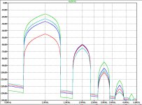
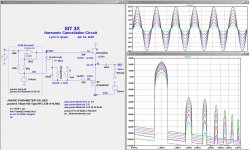
These plots show the spectra of the SIT current for different values of the degeneration resistor Rs. As you can see, it easy to obtain a variety of H3/H1 ratios. Can we get a SIT anti-phase H3 that cancels the PFET H3?
These plots show the spectra of the SIT current for different values of the degeneration resistor Rs. As you can see, it easy to obtain a variety of H3/H1 ratios. Can we get a SIT anti-phase H3 that cancels the PFET H3?
Attachments
Last edited:
well, everything is possible, even Wooden Stove, as I'm told
I believe that question (of F3 cancellation) will bring you some joy and interesting time, and I have no doubt that of all of us, you'll get to results most promptly 🙂
ZM's Lazy
I believe that question (of F3 cancellation) will bring you some joy and interesting time, and I have no doubt that of all of us, you'll get to results most promptly 🙂
ZM's Lazy
Cancellation of H3 is an interesting thing. The Stasis 1 (1978) had a
positive phase H3 by virtue of slightly increased gain in the output stage
with current. Subtle adjustment of that circuit would yield a greater
null, but I found the "dynamic expansion" an attractive idea, even if
Harry Pearson didn't like it.
At the last BAF my talk, obscured by technical difficulties, had some examples
of the effects of degeneration on push-pull gain stages including bipolar
transistors, whose exponential character could be exploited for this sort
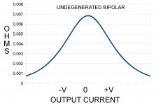
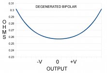
of thing. Attached are two curves of the output impedance of a bipolar
stage with and without degeneration. Without degeneration, we see
this expansion in the lower impedance with current, and with degeneration
we see the higher impedance. There would be an in-between
degenerating resistor value that is more flat, giving what Doug Self
would likely call optimal.
The attraction of running bipolars undegenerated is balanced by the
reliability issues. There are a couple of amplifiers on the market which
attempt this, but it seems that the resistors have been moved to the
Bases instead and there have still been some problems.
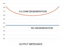
By contrast, square law devices like fets and tubes can achieve a
a more consistent output impedance without degeneration, as seen
in the 3rd image.
positive phase H3 by virtue of slightly increased gain in the output stage
with current. Subtle adjustment of that circuit would yield a greater
null, but I found the "dynamic expansion" an attractive idea, even if
Harry Pearson didn't like it.
At the last BAF my talk, obscured by technical difficulties, had some examples
of the effects of degeneration on push-pull gain stages including bipolar
transistors, whose exponential character could be exploited for this sort
of thing. Attached are two curves of the output impedance of a bipolar
stage with and without degeneration. Without degeneration, we see
this expansion in the lower impedance with current, and with degeneration
we see the higher impedance. There would be an in-between
degenerating resistor value that is more flat, giving what Doug Self
would likely call optimal.
The attraction of running bipolars undegenerated is balanced by the
reliability issues. There are a couple of amplifiers on the market which
attempt this, but it seems that the resistors have been moved to the
Bases instead and there have still been some problems.
By contrast, square law devices like fets and tubes can achieve a
a more consistent output impedance without degeneration, as seen
in the 3rd image.
Attachments
I'm in trouble if I stumble on working washing machine, older type, with visible drum from front side
it could easily happen that I'm staring for entire program, sorta hypnotized
I'm same hypnotized while even just thinking how SIT and Mosfet are working in DEFiSIT, without any source resistance in between
it was interesting to pursue measurements and sound test of few iterations ( with added resistance in sources) ......... but now ......... I'm in leaking state ......
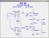
Proof of SIT-3 Harmonic Cancellation Concept
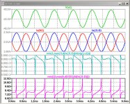
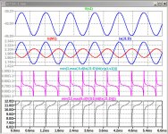
The schematic below show a proof of concept of SIT-3 harmonic cancellation without degeneration of the PFET M1. In this circuit, the gate bias of M1 is offset from that of J1 by Vgsoff and the modulation AC modulation from the input is attenuated by a factor of A. I found a combination of the parameters Vbias, Vgsoff, and A that produces nearly complete harmonic cancellation. WOW, look at these plots!!
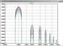
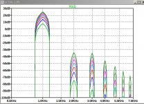
The first set of plots are the harmonic spectra for an 8R load at 1W, 4W, 9W, 16W, 25W, 36W and 49W. The second are the same into a 4R load.
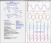
The 4th image show waveforms for 1W 8W. The 5th image show waveforms for 1W 4W.
THD%
Rload 1W 4W 9W 16W 25W 36W 49W
8R .007 .016 .028 .044 .067 .10 .15
4R .008 .017 .027 .041 .060 .08 .12
The next step is to convert this proof of concept into a practical circuit.
The schematic below show a proof of concept of SIT-3 harmonic cancellation without degeneration of the PFET M1. In this circuit, the gate bias of M1 is offset from that of J1 by Vgsoff and the modulation AC modulation from the input is attenuated by a factor of A. I found a combination of the parameters Vbias, Vgsoff, and A that produces nearly complete harmonic cancellation. WOW, look at these plots!!
The first set of plots are the harmonic spectra for an 8R load at 1W, 4W, 9W, 16W, 25W, 36W and 49W. The second are the same into a 4R load.
The 4th image show waveforms for 1W 8W. The 5th image show waveforms for 1W 4W.
THD%
Rload 1W 4W 9W 16W 25W 36W 49W
8R .007 .016 .028 .044 .067 .10 .15
4R .008 .017 .027 .041 .060 .08 .12
The next step is to convert this proof of concept into a practical circuit.
Attachments
-
 SIT3X-Ibias-2A0-Vb-50V-Rload-4R-waves.jpg222.8 KB · Views: 174
 -
 SIT3X-Ibias-2A0-Vb-50V-Rload-8R-waves.jpg215.2 KB · Views: 153
 -
 SIT3X-Ibias-2A0-Vb-50V-Rload-4R-spectra.jpg130.5 KB · Views: 162
 -
 SIT3X-Ibias-2A0-Vb-50V-Rload-8R-spectra.jpg132.7 KB · Views: 273
 -
 SIT3X-Ibias-2A0-Vb-50V-Rload-8R.asc.jpg99.3 KB · Views: 428
Yup, we cheat all the time in simulations. Can we figure out a practical circuit that approximates the cheat?
OTOH, you might get lucky and find a PFET which has exactly the right Vgs and gm at the operating point. Apparently that is what PAPA did with DEFiSIT. Good luck is the search.
You have DEFiSIT measurements somewhere in SissySIT thread (one of them)
I don't remember exact post, of course
they are not comparable with that sim of yours 🙂
I don't remember exact post, of course
they are not comparable with that sim of yours 🙂
Here is an image and a standalone LTSPICE .asc file for the SIT-3 harmonic cancellation simulation. I am still trying to figure out why it works so well and how to make a practical circuit without needing transformer with a weird winding ratio.
Have fun "tweaking" the simulation.
Have fun "tweaking" the simulation.
Attachments
Plausible Circuit for SIT-3 Harmonic Cancellation
Here is a circuit that looks plausible, but requires a front end to drive the output stage.
The plots show waveforms and spectra for 1kHz 8R load at 1W, 4W, 9W, 16W, 25W, 36W, and 49W.
Really good result.
Here is a circuit that looks plausible, but requires a front end to drive the output stage.
The plots show waveforms and spectra for 1kHz 8R load at 1W, 4W, 9W, 16W, 25W, 36W, and 49W.
Really good result.
Attachments

I am struggling to figure out how to drive the gates at these power levels. I also have no idea about the biss stability.
One option is a FirstWatt SIT-3 input stage. The maximum output level for the Jensen JT-123-FLPCH to +20dBu for 2-windings in series for the inputs and outputs. I do not know what the limit would be for the auto-transformer driven by 1 winding. A best case case of +26dBu would be about 20V peak, or 25W into 8R. Perhaps that would be a good starting point, but the devices can go a lot higher in power.
Another alternative is a BA-3, XA.8, or XA25 style front-end, without feedback from the output stage.

The big chips like 2SK182ES and THF-51S need a low source impedance.
For bandwidth getting up toward 100 KHz,
Common Source operation with CCS bias, you want 50 ohms or less.
Common Drain with a CCS bias, 600 ohms is low enough.
CS or CD biased by a mu follower, you need lower than these figures.
For bandwidth getting up toward 100 KHz,
Common Source operation with CCS bias, you want 50 ohms or less.
Common Drain with a CCS bias, 600 ohms is low enough.
CS or CD biased by a mu follower, you need lower than these figures.
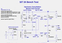
Below is a bench test circuit for the a SIT-3 style amplifier with adjustments to achieve harmonic cancellation. I plan to use an spare, very low distortion "XA-25 like" amplifier to drive the gates.
The circuit simulates very well, but I am awaiting IXYS FETs before I can can start bench testing.
The circuit simulates very well, but I am awaiting IXYS FETs before I can can start bench testing.
Attachments
ZM: What was your experience with 2SK182ES and IXYS pucks regarding temperature stability?
I am considering modifying an XA25-like amplifier, which has drain sense optocoupler bias control, and a front-end capable of driving the 2SK182ES and IXYS pucks.
I am considering modifying an XA25-like amplifier, which has drain sense optocoupler bias control, and a front-end capable of driving the 2SK182ES and IXYS pucks.
having proper heatsinking capacity, I found big SITs surprisingly well behaved with fixed gate bias, same applies to big Puck in Schade concoction
I believe I wrote some numbers in Singing Bush thread , but problem is my notorious lack of systematization, besides fact that now is 03:30 in my neck of wood ..... so , if you want me to look for any data, it'll wait for tomorrow
I believe I wrote some numbers in Singing Bush thread , but problem is my notorious lack of systematization, besides fact that now is 03:30 in my neck of wood ..... so , if you want me to look for any data, it'll wait for tomorrow
- Home
- Amplifiers
- Pass Labs
- SIT measurements, Mu Follower, and amplifier build