You are doing it wrong for the other side.
For fully balanced operation you use only IN+ on each side. IN- is grounded on both sides. That is why you don't need to change the resistors values.
I attached connection diagram.
Yes XLR pin 1 goes to chassis ground. Pin 1 of XLR is for shielding only, doesn't carry any return signal. You can experiment by connect it to preamp GND sometimes works better.
And yes both IN- of the preamps are connected to PS ground. First make ground connection between both sides then a wire from this connection to PS ground.
To bounce off mareli's helpful advice, I've taken the liberty of expanding the original sketch in Post #1991 and reflect it back here for comment. I'm finding my way when it comes to wiring up boards for balanced operation. I've scoured the thread and there's a bit of confusion that pops up because Wayne's clever design permits Balanced In->SE Out.
I'm interested in Balanced In->Balanced Out and that is what the sketch seeks to describe from input to output. Subsequently, I'm seeking input from those more knowledgeable with the plan of avoiding frustration, a melt down or a magic smoke party after the solder has cooled and the power gets turned on.
The sketch includes reference to source documents where relevant for clarity and added notes to suit. Hopefully, this will help another person like myself who's dipping their toe in balanced waters.
Constructive thoughts please. Thanks..

Attachments
Last edited:
I don't currently have a BA2018 but simulations show it is unity gain stable.
The feedback resistor and the 10K to ground are both changed to 100K and the 100 Ohm input resistor also. Simulations are pretty trustworthy on this but YMMV
Thank you for the answer Wayne. So that I don't screw this up, can you help me understand how the feedback resister and the input resister map to the schematic please? I assume the 10K to ground is R17.
To bounce off mareli's helpful advice, I've taken the liberty of expanding the original sketch in Post #1991 and reflect it back here for comment. I'm finding my way when it comes to wiring up boards for balanced operation. I've scoured the thread and there's a bit of confusion that pops up because Wayne's clever design permits Balanced In->SE Out.
I'm interested in Balanced In->Balanced Out and that is what the sketch seeks to describe from input to output. Subsequently, I'm seeking input from those more knowledgeable with the plan of avoiding frustration, a melt down or a magic smoke party after the solder has cooled and the power gets turned on.
The sketch includes reference to source documents where relevant for clarity and added notes to suit. Hopefully, this will help another person like myself who's dipping their toe in balanced waters.
Constructive thoughts please. Thanks..
I have pin 1 wired to power supply ground, not chassis. On my build wiring it this way eliminated all audible hum.
Power Supply Current Delivery Capacity
So, to be clear, then a single stereo board to output SE service would come to double this number ('ish)? Worst case.
Furthermore - for a balanced stereo build, and accounting for this basis, I'd be looking at a supply that can deliver ~400 mA to accommodate probable worst case duty. Sound about right?
While we're discussing power supply, I've never really figured out how to sum current draw based on the components. What's the maximum draw for the circuit? Would 100 mA give enough headroom for safe operation?
Yes.
So, to be clear, then a single stereo board to output SE service would come to double this number ('ish)? Worst case.
Furthermore - for a balanced stereo build, and accounting for this basis, I'd be looking at a supply that can deliver ~400 mA to accommodate probable worst case duty. Sound about right?
Last edited:
Helios Bi-Polar PSU (REV B)
Hey guys just a quick heads up that I have now finished REV B of my Bi-Polar PSU boards. The official name is Helios. More info below:
Meet Helios! Bi-Polar power supply REV B boards coming soon! – audiosy.net
Hey guys just a quick heads up that I have now finished REV B of my Bi-Polar PSU boards. The official name is Helios. More info below:
Meet Helios! Bi-Polar power supply REV B boards coming soon! – audiosy.net


Awesome re outputs.
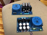
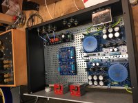
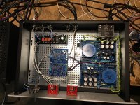
I applied power & it works great...dead silent. Ran for a couple hours on the test system
and delighted by the bass. Adjusted outputs to as close to zero..it’s sensitive for sure...moves around +/- but pretty stable. I can blow on the board and it changes.
I’ll splice into main sys and see what it does...great stuff y’all are sharing here..Thanks
Attachments
- Home
- Amplifiers
- Pass Labs
- Wayne's BA 2018 linestage