This is what I do. Once the unit has been on a while, leave the cover on and stick the multimeter probes into and on the output RCA jacks. That way you can see where the offset is on each output when the temp is stable because it will drift when you take the cover off. Then adjust the pots only the amount you need to given the extra drift from the cover being off.
Maybe DC offset was not the correct term, I meant adjusting the pots as close to zero as possible.
Kind of thought it was as simple as the answer above, just wanted to make sure before I put an eye out or something.
Thanks aljordan
Kind of thought it was as simple as the answer above, just wanted to make sure before I put an eye out or something.
Thanks aljordan
DC offset is the correct term, and it is the audio outputs you are measuring when adjusting. Board outputs or rca outputs won't make a difference. Just don't stick a multimeter lead into your eye, or drag a screwdriver across any board components.
Last edited:
I have a questions, I built the boards and everything powers on. I have +/-18 vdc on the rails. I powered up the board and the LED come on, DC voltage is stable at input stage. However when checking for Offset on each channel I show -0.2 mV and P1 does not seem to adjust offset up or down. Any suggestions on what to check or would it be okay to test.
Sorry my mistake, must have been in a hurry as i was checking offset at the wrong location. Was on the input side so obviously no offset adjustment would be read. I will continue to work on it and now time to make a case for it.
Progress...tiny wiring to go.
Hello Monk55, are those Khozmo attenuators?
One More
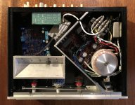
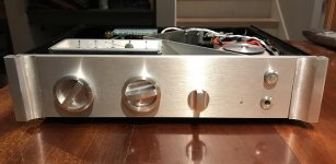
Hi All. Another build. Wanted to make it pretty compact. It's still pretty rough, and everything is floating inside right now.
Stock case, but with some cosmetic modifications. Volume/selector knobs inspired by a Nagra tape recorder. Diagonal internal division in unconventional, but was best way to fit things in.
- Tubecad bipolar PS, 18v; Antek tranny
- 5v switching PS for colored LEDs that will be used for positions on the selector
- Trough-like thing on left will hold multi-position switches, used to tweak volume of inputs to match levels
- Crossover for sub, knobs on back
- Balance using another multi position switch; just for subtle tweaks
A couple questions on grounding. I have star safety ground that will be screwed into the base plate.
1) Do I connect the signal ground to the safety ground and if so, is there a best place to connect, or just run input and output grounds to the star? Connect to ground directly, or with a resistor, or a thermistor, or a diode/bridge? There are so many different ways of doing it and I can't make any sense out of the choices.
2) Regarding this anodized case, putting the ohmmeter on various points there's a lot of resistance from piece-to-piece. Not, I think , much of a shielded enclosure. Is there a best practice for tying them all together? Link panels together or star everything?
Any help appreciated.
Attachments
Last edited:
Hello Monk55, are those Khozmo attenuators?
Indeed they are. A bit spendy but I like um so far. Figured what the heck...we’ll see how long they last. Go.
Last edited:
Did you get the one with remote control? From what I can see from the picture you have two attenuator did you set it up so you have a separate volume control per channel?
Are you running balance in and unbalance out?
Thanks!!
Are you running balance in and unbalance out?
Thanks!!
Availability of PCBs
Hi,
Does anyone here have an idea of when new PCBs for the BA2018 might be back in stock in the store?
Thanks,
Brad
Hi,
Does anyone here have an idea of when new PCBs for the BA2018 might be back in stock in the store?
Thanks,
Brad
New stocks for WAYNE'S BURNING AMP 2018 LINESTAGE pcbs have arrived at the warehouse and are currently being processed. They will most probably be available by next week or so..
Please sign up to get notified by clicking the "Email when available" button and add in your email address in the link below:
Wayne's Burning Amp 2018 Linestage – diyAudio Store
Please sign up to get notified by clicking the "Email when available" button and add in your email address in the link below:
Wayne's Burning Amp 2018 Linestage – diyAudio Store
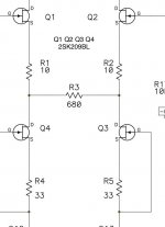
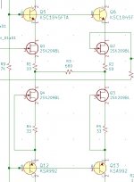
I designed my pcb all jacked up and doesn't work. Now that I found my mistakes and corrected them, I found some other stuff.... I want to make sure I have dotted all my i's before I get my 2nd batch made. My question is, which of these two are correct?
Attachments
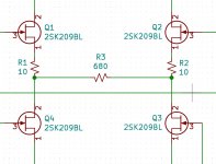
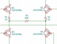
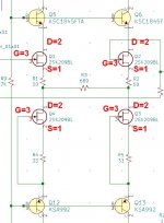
JFet symbol is not good, so we can't tell, especially not knowing whatdf 2 and 3 means
in any case, Drain goes up, Source goes down
in any case, Drain goes up, Source goes down
- Home
- Amplifiers
- Pass Labs
- Wayne's BA 2018 linestage