I think I was in the wrong range? Salas will
see it.... 😉
Given the narrow limits of Peak's DCA Pro for Ic max & Vce max it was a good range
building Waynes linestage
Hello members,
some TOSHIBA TTA/TTC004B - measurements.
And I am waiting for some final parts to finish the pcb-stuffing.
Greets
Dirk
Hello members,
some TOSHIBA TTA/TTC004B - measurements.
And I am waiting for some final parts to finish the pcb-stuffing.
Greets
Dirk
Attachments


building Waynes linestage
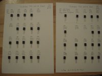
TOSHIBA TTC004B / TTA004B measurements (20 devices of each)
TTC004B:
device: H/FE V/BE V/CE SAT
1 181 0,713V 0,014V
2 170 0,711V 0,015V
3 181 0,716V 0,014V
4 180 0,713V 0,015V
5 184 0,713V 0,015V (used)
6 184 0,713V 0,015V (used)
7 174 0,713v 0,015V
8 169 0,711V 0,015V
9 180 0,715V 0,014V
10 183 0,712V 0,015V
11 174 0,715V 0,015V
12 182 0,714V 0,015V
13 177 0,710V 0,014V
14 172 0,711V 0,015V
15 172 0,712V 0,015V
16 179 0,712V 0,015V
17 174 0,711V 0,015V
18 174 0,711V 0,015V
19 172 0,712V 0,015V
20 179 0,711V 0,015V
TTA004B:
1 218 0,703V 0,017V
2 214 0,703V 0,016V
3 197 0,703V 0,016V
4 225 0,689V 0,017V
5 225 0,699V 0,016V
6 206 0,699V 0,016V
7 198 0,698V 0,016V (used)
8 197 0,700V 0,017V (used)
9 224 0,694V 0,017V
10 207 0,699V 0,017V
11 206 0,699V 0,016V
12 237 0,699V 0,015V
13 204 0,697V 0,016V
14 221 0,700V 0,016V
15 217 0,699V 0,016V
16 206 0,698V 0,016V
17 223 0,696V 0,016V
18 203 0,699V 0,016V
19 210 0,691V 0,016V
20 207 0,699V 0,016V
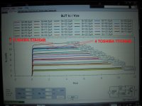
TTA004B have most often higher H/FE than TTC004B.
Greets
Dirk
:
TOSHIBA TTC004B / TTA004B measurements (20 devices of each)
TTC004B:
device: H/FE V/BE V/CE SAT
1 181 0,713V 0,014V
2 170 0,711V 0,015V
3 181 0,716V 0,014V
4 180 0,713V 0,015V
5 184 0,713V 0,015V (used)
6 184 0,713V 0,015V (used)
7 174 0,713v 0,015V
8 169 0,711V 0,015V
9 180 0,715V 0,014V
10 183 0,712V 0,015V
11 174 0,715V 0,015V
12 182 0,714V 0,015V
13 177 0,710V 0,014V
14 172 0,711V 0,015V
15 172 0,712V 0,015V
16 179 0,712V 0,015V
17 174 0,711V 0,015V
18 174 0,711V 0,015V
19 172 0,712V 0,015V
20 179 0,711V 0,015V
TTA004B:
1 218 0,703V 0,017V
2 214 0,703V 0,016V
3 197 0,703V 0,016V
4 225 0,689V 0,017V
5 225 0,699V 0,016V
6 206 0,699V 0,016V
7 198 0,698V 0,016V (used)
8 197 0,700V 0,017V (used)
9 224 0,694V 0,017V
10 207 0,699V 0,017V
11 206 0,699V 0,016V
12 237 0,699V 0,015V
13 204 0,697V 0,016V
14 221 0,700V 0,016V
15 217 0,699V 0,016V
16 206 0,698V 0,016V
17 223 0,696V 0,016V
18 203 0,699V 0,016V
19 210 0,691V 0,016V
20 207 0,699V 0,016V
TTA004B have most often higher H/FE than TTC004B.
Greets
Dirk
:
Attachments
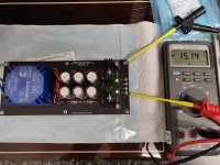
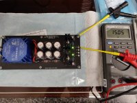
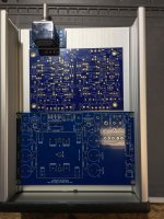
She lives. My PSU is up and running. Now just need one or two BA Linestage boards. If anyone here wants a couple of these PSU boards in exchange for sending me a couple of the Linestage PCBs then first to comment with interest I'll PM my request and reasons why. 😊
Attachments
building Waynes linestage
Hello members,
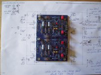
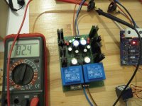
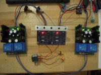
at the moment I made the first start of my version of Waynes linestage.
All looks very promising. The baby is cooking....
Perhaps a first listen this night? 😀
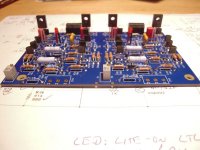
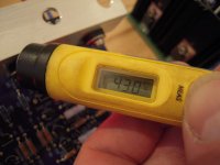
The Toshiba TTA/TTC004B got a 15Ohm bias resistor each. Temperature
of the Toshibas is between 39 C and 43C (with the help of my little heatspreader).
Without the heatspreader they were at around 60C temp.
Offset is at -2,4mV and 0,0mV (pretty stable).
The story continues....
Greets
Dirk
Hello members,
at the moment I made the first start of my version of Waynes linestage.
All looks very promising. The baby is cooking....
Perhaps a first listen this night? 😀
The Toshiba TTA/TTC004B got a 15Ohm bias resistor each. Temperature
of the Toshibas is between 39 C and 43C (with the help of my little heatspreader).
Without the heatspreader they were at around 60C temp.
Offset is at -2,4mV and 0,0mV (pretty stable).
The story continues....
Greets
Dirk
Attachments
-
 Waynes_linestage-+first start-temp-Toshiba.jpg79.4 KB · Views: 403
 -
 Waynes_linestage-+first start-offset-right.jpg112.9 KB · Views: 399
 -
 Waynes_linestage-+first start-offset-left.jpg117.3 KB · Views: 532
 -
 Waynes_linestage-+first start2.jpg111.6 KB · Views: 543
 -
 Waynes_linestage-+first start1.jpg118.8 KB · Views: 493
Wonderful!! Looks very nice! 
Before listening, the -IN needs to be attached to GND with a single-ended source.
Before listening, the -IN needs to be attached to GND with a single-ended source.
building Waynes linestage
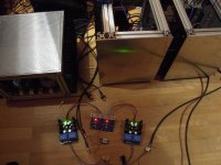
I could not resist! 🙄
Playing with my 50W-SE-Schade-amp.....
Dirk
Thanks Wayne!!!! Cheers!
I could not resist! 🙄
Playing with my 50W-SE-Schade-amp.....
Dirk
Thanks Wayne!!!! Cheers!
to 6L6
You are right! Have to connect -in to ground🙄
Thanks for the hint. But plays music....
Greets
Dirk
You are right! Have to connect -in to ground🙄
Thanks for the hint. But plays music....
Greets
Dirk
Thanks!, ItsAllInMyHead.
It sounds really good! Completely different character than the B1 Nutube.
Very detaillled and clear. But I have to listen more for a real statement.
Greets
Dirk
It sounds really good! Completely different character than the B1 Nutube.
Very detaillled and clear. But I have to listen more for a real statement.
Greets
Dirk
Wow. Now I hear what all the fuss has been about. Smooth, detailed mids and highs, articulate bass. The sonic control exhibited is akin to an iron fist in a velvet glove. The best of the best. Takes my breath away and takes my system to the next level. Thank you, Wayne, for sharing this exceptional discreet component circuit design with the DIY community!
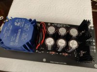
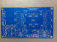
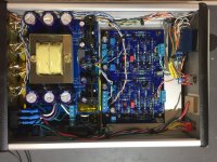
For a power supply, I used KiCad to design a stand alone version of Mr. Coburn's Whammy linear regulated power supply. I designed the PCB to slide into the same Hammond 1455T2201 chassis he used for that project, although it could go into others. The BA2108 board and custom PS board leave enough space in the Hammond for an Alps RK27 pot, power LED and switches on the front panel as well as I/O jacks and filtered IEC inlet on the rear. I used red LED referencing for the PS regulators, which yields approximately +/- 17 V when using 18 V dual transformer secondaries.
I added terminal blocks, a 115/230 V transformer primary selector switch, safety grounding with bridge and thermistor as well as an RF bypass to the chassis ground, all on board, an on board line fuse, power switch connection and a dedicated power LED dimming circuit tapped directly off the transformer secondary (thank you Mark Johnson). I figured these options could be bypassed with jumpers and/or off-board wires soldered directly to the PCB pads if I chose not to use them. The PCB accommodates either the Triad FS36-550 dual bobbin transformer or the Amgis/Talema 70054K toroid (or equal). The Talema would make things a bit tighter but not impossible at the rear panel.
My build uses the Triad transformer but without the selector switch and without the filtered and fused version of the IEC inlet. I used the on-board fuse option. The build is dead quiet, exhibiting the inky quietness of a really high quality linear regulated supply. After burn in and setting the DC offset, I get a bit of wandering DC on the outputs, +/- 1 to 2 mV above and below the zero DC point. I don't think 1 or 2 mV DC when amplified is going to damage my loudspeakers. I can hear the benefit of the DC coupling of this circuit and how it contributes to the coherence of the sound without any detraction that would be caused by using a DC servo circuit. It sounds better for the same reason that using little or no NFB can sound better if done right. Scope shows no oscillation.
This was my first PCB design project and it was great fun. It takes the hobby into a satisfying new dimension for me. PCB fab from China is remarkably inexpensive with a quick turn around. This board was a bit challenging due to the AC line voltage and transformer mounting. I believe the board is safe, given the CL-60 and bridge rectifier safety bypass from circuit ground to the chassis/line cord ground. I did add Kapton tape under the line voltage areas of the board and in a few other places where line voltage was exposed. Not shown is a nylon 8-32 screw up from the bottom of the chassis and into the unused center (Amgis) transformer mounting hole to keep the power supply PCB from sliding around in the chassis slots. I was careful to remove the non-conductive aluminum anodizing when wiring together the main chassis, front and rear panels for grounding continuity. The sliding top panel is the only metal that remains isolated but with almost 10mm clearance to everything below, I really see no chance of contact between it and any circuit components.
Attachments
That is a fantastic example of big things in small packages! Thank you for the information re: your progression into trying your hand at laying out and sourcing your own PCB. I've been reading up a bit, but haven't taken the plunge.
Bravo!
Bravo!
@avdesignguru, assign a "HV" net to all your 115V & 230V traces, and give it a much larger clearance. Otherwise, over time airborne contaminants can collect on the board causing leakage at higher voltages. This is called "creepage", and you can find lots of creepage calculators on the web to help you come up with a value.
Note: for the most part none of them agree with each other. 😉 FWIW, I use 2mm but I'm an amateur too....
Note: for the most part none of them agree with each other. 😉 FWIW, I use 2mm but I'm an amateur too....
Avdesignguru, congratulations on your bravery! And a second round of congratulations on your very successful design. Attaboy and goodonya.
I have used +/- 24 with the small outputs and 27R R11 R12 - it works beautifully.
Bigger output devices should have more current, change to 15R as suggested and enjoy!
PSU voltage is very forgiving, 15-24 will work well. I have used 15, 18, 24V all successfully.
Super regulator and lt3042 both max 15v output so any changes we need to make to use with 15v?
LT4320 able to give max 200ma. So anybody know current consumption of per rail on mono board?
And final question 60mW is enough for resistors?
Folks:
I don't really understand the advantages of using KSA1220 and KSC2690 at Q10, Q20 and Q8, Q20, respectively, but I do have two of each available if they are worthwhile substitutions. Do they need to be matched in any way? And if I do use them, do I understand correctly that R11, R12, R32 and R33 should all be changed to 15R / 1W? At what point does using larger output devices become worthwhile? I expect my rails to be running at just over 18+/- VDC.
Regards,
Scott
Last edited:
- Home
- Amplifiers
- Pass Labs
- Wayne's BA 2018 linestage