Can you see the plan?
This is coming together now. Horrible wet day outside but I need to go out and get some Ally strip to improve heat sinking from the filter/rectifier board on the base to the sides. Toroids with base plate ordered are the exact same quoted 150mm width as the Mini Dissipante interior space so some minor hole widening of the case brackets may be required once they arrive. Hole cut in the top plate 160mm to give 5mm clearance and ventilation.
Top brackets have been cut short of the top hole but left long enough to suspend the transformer base 20mm below the top leaving 40mm poking through.


I'd have liked to make them handed but I need right angled IEC plugs to get them tucked up tight against the wall. The plugs are handed one direction only so the sockets got placed dead centre.
I plan to run the DC power supply from the DC jack straight down between the AC switch and IEC inlet to keep it very short - or would you make it longer and loop it out and around the AC? I have 10 amp hook up wire for this. I've got yards of adhesive copper strip (bought for wiring EL Wire) I could wrap that around the connector cables and use some shrink tubing would that work as a shield?
This is coming together now. Horrible wet day outside but I need to go out and get some Ally strip to improve heat sinking from the filter/rectifier board on the base to the sides. Toroids with base plate ordered are the exact same quoted 150mm width as the Mini Dissipante interior space so some minor hole widening of the case brackets may be required once they arrive. Hole cut in the top plate 160mm to give 5mm clearance and ventilation.
Top brackets have been cut short of the top hole but left long enough to suspend the transformer base 20mm below the top leaving 40mm poking through.
I'd have liked to make them handed but I need right angled IEC plugs to get them tucked up tight against the wall. The plugs are handed one direction only so the sockets got placed dead centre.
I plan to run the DC power supply from the DC jack straight down between the AC switch and IEC inlet to keep it very short - or would you make it longer and loop it out and around the AC? I have 10 amp hook up wire for this. I've got yards of adhesive copper strip (bought for wiring EL Wire) I could wrap that around the connector cables and use some shrink tubing would that work as a shield?
Given how good the ACA sounded as a simple stereo amp, I really wanted to try a pair as bridged mono blocks. Since I had modified the input and feedback resistors, I knew that a different resistor value would be required between channels to make a bridged amp. After some experimentation, I settled on a value of 68.1k from the left (-) output to the right input. My experience plus some other findings on the Pass forums suggest that the standard recommendation of using the same value as the feedback resistor is not the best way to go. For those who wish to bridge the standard configuration amp (v 1.6), I would recommend a value no more than 33k, and preferably 30.1k in order to get more symmetrical response between the two halves of the bridged amp.
As bridged mono, these amps are amazing! As expected, both dynamics and stereo separation improved, but the degree of improvement is both subtle and profound. The enhanced dynamics open a clear window into the details of each recording, without throwing them in your face. The soundstage has improved to the point where, on good recordings, the 3D image is completely separated from the speakers.
Having the pair of bridged ACAmps has induced many extended listening sessions, and revisiting quite a few favorite albums. On many recordings, I'm hearing details that I hadn't heard before, and some of my favorites just beg to be played over and over again. This quality is a testament to the simple and elegant circuit design, which responds well to careful device selection.
Though the improved dynamics have been quite satisfying at my usual listening levels, the medium efficiency of the old Vandersteens still has me running the amps close to flat-out much of the time. To address what I perceived as a slight upper treble harshness, I eventually added a 10 pF Silver Mica cap in parallel with the 90.9k feedback resistor on each board. While the effect of this is subtle, the ease of presentation makes it worthwhile.
That's all I've done for now. While I originally was thinking of building a linear power supply to replace the SMPS bricks, I'm happy enough with the way things are to start working on other projects. Given the revealing nature of the amps, I'm sufficiently motivated to finally build an improved power supply for the NAC 82. I'm hoping that a DIY version of a dual HiCap DR to replace my single Olive series HiCap will be a worthwhile effort.
As for other NP amps, I already have an F4 clone in the works, and am planning an Aleph J, and even an M2X somewhere down the road. Too much fun!
for parallel mode, the bridge resistor is not related right?
the 68.1k resistor is only for bridge mono.
Correct. With this arrangement, the switch on the rear panel is used to select plain stereo mode or bridged monoblock operation. For paralleled monoblocks, the switch is left in stereo mode (68.1k resistor is unconnected), and the parallel connections are made with external wires and a jumper in the XLR connector. I showed how I did this in post #37for parallel mode, the bridge resistor is not related right?
the 68.1k resistor is only for bridge mono.
There is also a more recent thread, Monoblock ACA bridged mono <=> parallel mono at the flick of a switch, on how to use a switch to select between two monoblock modes of operation.
So - can the ACA take 25volt without modification or would i need a couple of resisters to work as a voltage divider to drop the output back to 24 volt? I've got wall warts and bricks all over my system now - time to tidy up replace and upgrade. I'm considering same cases as ACA with a hole in the top with a Chrome Toroidy showing through")
I've run ACA at 30V. No modifications were required, obviously check temperatures, this was not a problem for me.
Follow-up, trying to follow
TungstenAudio,
I've been following this thread as closely as I could, reading parts of it over and over again (it's fun because it's complicated), and now I have decided to give it a try. Since I'm not yet understanding what's going on, I'm sourcing the parts you recommend (marked in red). Prefer to be on the safe side.
Of course there are gazillions of questions which are dead-obvious to most of this community, so I'll focus on this one concerning caps:
Why did you choose
Nichicon KG / RNL / RL8
and not MKZ downwards?
Was it for rational economic/size reasons, or is there a more technical issue?
(to put it otherwise, would it be wrong or senseless to go with UKZ and use
C2: 1000 uF 25V (1000 uF 16V)
C4: 1000 uF 50V (100 uF 35V)
Thank you!
david
I have attached a marked up schematic of the enhanced ACA which has been the basis for my latest builds.
TungstenAudio,
I've been following this thread as closely as I could, reading parts of it over and over again (it's fun because it's complicated), and now I have decided to give it a try. Since I'm not yet understanding what's going on, I'm sourcing the parts you recommend (marked in red). Prefer to be on the safe side.
Of course there are gazillions of questions which are dead-obvious to most of this community, so I'll focus on this one concerning caps:
Why did you choose
Nichicon KG / RNL / RL8
and not MKZ downwards?
Was it for rational economic/size reasons, or is there a more technical issue?
(to put it otherwise, would it be wrong or senseless to go with UKZ and use
C2: 1000 uF 25V (1000 uF 16V)
C4: 1000 uF 50V (100 uF 35V)
Thank you!
david
Last edited:
My general preferences for making component substitutions include using parts that are relatively easy to fit in the original location. The 4700 uF KG output cap is an easy fit on the PCB, as it has the same diameter and snap-in lead spacing. The RNL and RL8 aluminum organic polymer parts were chosen for mechanical fit in addition to improved characteristics. The 1000 uF, 16V part has a small diameter that is also easy to fit on the new boards that Rudi designed. The 100 uF, 35V part has a diameter and lead spacing that fits into the C4 location, and has a higher value. The organic polymer parts seem to have similar benefits as the Elna Silmics.
If you prefer using the UKZ family of Nichicon capacitors, those are very good parts as well. They do tend to be larger in diameter that other makes of parts with the same values, so I don't use them as often with manufactured PCBs.
If you prefer using the UKZ family of Nichicon capacitors, those are very good parts as well. They do tend to be larger in diameter that other makes of parts with the same values, so I don't use them as often with manufactured PCBs.
My general preferences for making component substitutions include using parts that are relatively easy to fit in the original location. The 4700 uF KG output cap is an easy fit on the PCB, as it has the same diameter and snap-in lead spacing. The RNL and RL8 aluminum organic polymer parts were chosen for mechanical fit in addition to improved characteristics. The 1000 uF, 16V part has a small diameter that is also easy to fit on the new boards that Rudi designed. The 100 uF, 35V part has a diameter and lead spacing that fits into the C4 location, and has a higher value. The organic polymer parts seem to have similar benefits as the Elna Silmics.
If you prefer using the UKZ family of Nichicon capacitors, those are very good parts as well. (...)
Thank you, TungstenAudio, for clarifying a bit. If I get you right, you didn't choose those parts for "very specific audio" reasons, but rather for technical ones like fitting / diameter, and values?
I think I'll just (have to
) go for both and see if there's a (audible) difference.(...) They do tend to be larger in diameter that other makes of parts with the same values, so I don't use them as often with manufactured PCBs.
BTW, this sounds like you're quasi living in electronics
Last edited:
By all means, definitely try your own selection of parts, and share the results.
I did choose the KG / RNL / RL8 parts for audio performance as well. I chose not to add film capacitors underneath the board for the ACA, as I wanted to preserve the simplicity of construction for potential new builders. The ACA, after all, is intended as an entry level build. I wanted to suggest some simple (and inexpensive) modifications that would fit with the intended purpose of the amp.
I did choose the KG / RNL / RL8 parts for audio performance as well. I chose not to add film capacitors underneath the board for the ACA, as I wanted to preserve the simplicity of construction for potential new builders. The ACA, after all, is intended as an entry level build. I wanted to suggest some simple (and inexpensive) modifications that would fit with the intended purpose of the amp.

Careful there, the potential for complications in DIY can be great.
This is the power supply for my next amp (or two). Just like poor Johm McClane who was hoping for a simple Xmas party and got into something much deeper...
Those look great.
(Something tells me I hit my weak point with this John mc lane in many aspects)
Somehow this attachment disappeared from the previous post.
I've a question: in your layout you say
«R4 0.50
Or: leave R3 & R4 @ 0.68, add 2.0 in parallel.»
should only R4 be changed to R4, or R3 + R4?
(and: I don't understand »add 2.0 in parallel« ... sorry)
Thanks very much!
david
Last edited:
The first option is R3 @ 0.68 and R4 @ 0.50
Another option is R3 and R4 @ 0.56
If your board already has R3 and R4 installed @ 0.68, then you can add 2.0 in parallel with one of those.
Check out the combined resistance of the above options, and you will see they are all close to each other.
I like to use the formula 1/Rtotal = 1/R1 + 1/R2 + ... + 1/Rn
Last edited:
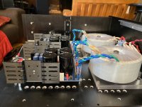
Big ACA Power Supply
Well got one of a pair of power supplies up and running nicely. I thought I might have damaged one of the pair of filter boards a couple of weeks ago whilst working on it late at night - dumb mistake and magic smoke was released as soon as it was hooked up to an amp. Replacement board on the way. Here's the picks of the completed one. Two ACA cases bolted together using 10mm standoffs.


Well got one of a pair of power supplies up and running nicely. I thought I might have damaged one of the pair of filter boards a couple of weeks ago whilst working on it late at night - dumb mistake and magic smoke was released as soon as it was hooked up to an amp. Replacement board on the way. Here's the picks of the completed one. Two ACA cases bolted together using 10mm standoffs.
Last edited:
That looks like it is coming along nicely. The end result with the chrome cased transformer is quite stunning.
I am curious about the design of the power supply. Is there some sort of capacitance multiplier following the filter caps and discrete rectifier diodes?
I am curious about the design of the power supply. Is there some sort of capacitance multiplier following the filter caps and discrete rectifier diodes?
Last edited:
That looks like it is coming along nicely. The end result with the chrome cased transformer is quite stunning.
I am curious about the design of the power supply. Is there some sort of capacitance multiplier following the filter caps and discrete rectifier diodes?
Since i'm still learning i bought off the peg on this occassion:
ULN-PS7 Ultra Low Noise, 6.0A High Current Power Supply for High Quality Audio | eBay
You can buy without the heatsink on the listing.
@Tungstenaudio
Have you experimented with more powerful output MOSFETS? I think Vishay has something like IFR520 or something (can’t remember the number designation) that, I think, offer higher output. I ask because I think I prefer true single-ended output amps to the Bridged version. Basically, I would love to get 10 clean watts out of a single ended stereo ACA into my 12 ohm Zu speakers.
Have you experimented with more powerful output MOSFETS? I think Vishay has something like IFR520 or something (can’t remember the number designation) that, I think, offer higher output. I ask because I think I prefer true single-ended output amps to the Bridged version. Basically, I would love to get 10 clean watts out of a single ended stereo ACA into my 12 ohm Zu speakers.
Last edited:
So far the most powerful Mosfets I’ve used in my ACAs are the IRFP140. Run with 28V, a single stereo amp had better sound than my two original ACAs run as parallel mono blocks. I also bought sets of IRFP150 and even IRFP044N. I think the more powerful devices can definitely make a difference, and will work best with higher supply voltage. I did have really good results using FQH44N10 Mosfets in my F6. They have better performance numbers than the IRFP150.
The changes I’ve made to R3 and R4 are important to allow higher bias current. I would suggest 0.56 Ohms for higher power. It’s also best to use a dropping resistor of 499 Ohms above the input JFet with the higher supply voltage.
The changes I’ve made to R3 and R4 are important to allow higher bias current. I would suggest 0.56 Ohms for higher power. It’s also best to use a dropping resistor of 499 Ohms above the input JFet with the higher supply voltage.
- Home
- Amplifiers
- Pass Labs
- ACA amp with premium parts