It depends on your buffer cards. w/o input card everything is fine.
I know of at least two totally safe cards Tucson and IPS7 others maybe closer but may also be completely ok. I presume someone has put together a list of cards with a 'safe up to +/- xxx VDC PS' spec.
I know of at least two totally safe cards Tucson and IPS7 others maybe closer but may also be completely ok. I presume someone has put together a list of cards with a 'safe up to +/- xxx VDC PS' spec.
I’m getting a steady 26.8v + and - using an Antek 3218 with the store’s v3 Universal PS boards with the diode section. My mains is 125v. Is this a problem or am I in range for the M2x?
Have you hooked your PSU up to a load yet? The voltage will sag some when hooked up to the amp boards.
That being said, many of us are using a few more volts via the SLB PSU board. My voltage, under load is 25, near 26. (I am on the conservative side) I have not had issues with any of the many daughter boards. While I overbuilt the M2x boards, there is not extra room on the daughter boards to up-spec much. I “red pilled” my recent IPS6 cards with RNG60 resistors, but I don’t think it’s resistor failure that we are concerned about.
Find someone who owns all eleven IPS cards (if you count Moffett Field, Melbourne, and Black Forest) AND a variable mains transformer "Variac" rated for 500 VA or higher.
Figure out a way to give them a powerful incentive to measure each one of the eleven IPS cards, at two different values of power supply voltage. I would suggest (i) Vout= normal DC value without variac; (ii) Vout = normal DC value minus 3.5 volts, created by adjusting the AC mains to the M2x using the variac.
Depending upon the person, the "powerful incentive" might be fancy or hard-to-get beers or wines. It might be hard-to-get electronic components. It might be plain old money via PayPal. It might be lavish public praise on the diyAudio Forums. It might be a 6-month loan of one of your rare and expensive pieces of gear.
Now measure the DC voltage drop across every component on the IPS card. Fill out a two page report; page 1 has the voltage drops when (i) Vout = normal DC value without variac; Page 2 has the voltage drops when (ii) Vout = normal - 3.5V using variac.
Now use 9th grade algebra to create a simple linear equation, which expresses the voltage drop across a component, as a function of power supply voltage:
Shazam! That is EXACTLY the information you seek. An equation, based on actual measured data on actual M2x cards, which tells you the voltage stress on every component, for any power supply voltage which you may wish to contemplate. EXACTLY what you want.
{Why the voltage ACROSS component_number_J? Because that's what can potentially make component_J fail! If it's a resistor, the power it dissipates is set by the voltage ACROSS the resistor. You don't want V(end1, GND), you want V(end1, end2). Same for semiconductors: you don't want V(drain, GND) you want V(drain, source)! }
You may discover that some components on some boards, have a very small value of "Constant1" ... i.e., the V across those components is totally independent of power supply voltage. In fact I think you definitely WILL discover that the voltage across the supply terminals of some of the opamps on some of the IPS boards, is totally independent of power supply voltage. Whether your PSU puts out 21V or 37V, the opamp supply pins see the same unvarying voltage.
Have this highly incentivized person prepare a final document with eleven chapters, one chapter for each of the eleven IPS cards. Every chapter contains all equations for all components on that IPS card.
It's not like this is a GIGANTIC amount of work. The average number of components per board is 20 or so, thus a total of 40 voltage measurements are taken per board. (20 parts, twice each: because 2 different PSU voltages). If you are terribly, terribly slow / methodical, even at 5 minutes per measurement (!!!) that's only 200 minutes per board. Three and one third hours per board. You could do one board per afternoon easily, and still have time to perform all your other non-DIY-hobby activities too.
Figure out a way to give them a powerful incentive to measure each one of the eleven IPS cards, at two different values of power supply voltage. I would suggest (i) Vout= normal DC value without variac; (ii) Vout = normal DC value minus 3.5 volts, created by adjusting the AC mains to the M2x using the variac.
Depending upon the person, the "powerful incentive" might be fancy or hard-to-get beers or wines. It might be hard-to-get electronic components. It might be plain old money via PayPal. It might be lavish public praise on the diyAudio Forums. It might be a 6-month loan of one of your rare and expensive pieces of gear.
Now measure the DC voltage drop across every component on the IPS card. Fill out a two page report; page 1 has the voltage drops when (i) Vout = normal DC value without variac; Page 2 has the voltage drops when (ii) Vout = normal - 3.5V using variac.
Now use 9th grade algebra to create a simple linear equation, which expresses the voltage drop across a component, as a function of power supply voltage:
- V_across_component_number_J = (Constant1 * Power_Supply_Voltage) + Constant2
{Why the voltage ACROSS component_number_J? Because that's what can potentially make component_J fail! If it's a resistor, the power it dissipates is set by the voltage ACROSS the resistor. You don't want V(end1, GND), you want V(end1, end2). Same for semiconductors: you don't want V(drain, GND) you want V(drain, source)! }
You may discover that some components on some boards, have a very small value of "Constant1" ... i.e., the V across those components is totally independent of power supply voltage. In fact I think you definitely WILL discover that the voltage across the supply terminals of some of the opamps on some of the IPS boards, is totally independent of power supply voltage. Whether your PSU puts out 21V or 37V, the opamp supply pins see the same unvarying voltage.
Have this highly incentivized person prepare a final document with eleven chapters, one chapter for each of the eleven IPS cards. Every chapter contains all equations for all components on that IPS card.
It's not like this is a GIGANTIC amount of work. The average number of components per board is 20 or so, thus a total of 40 voltage measurements are taken per board. (20 parts, twice each: because 2 different PSU voltages). If you are terribly, terribly slow / methodical, even at 5 minutes per measurement (!!!) that's only 200 minutes per board. Three and one third hours per board. You could do one board per afternoon easily, and still have time to perform all your other non-DIY-hobby activities too.
Have you hooked your PSU up to a load yet? The voltage will sag some when hooked up to the amp boards.
No, this is just chugging along with no load. I didn’t want to hook it up if it was going to do harm. Would adding the “optional” pi resistors reduce voltage some? And anyway, how do I go from 18v from the secondaries and 24v after rectification (18 x 1.4 to get DC) to nearly 27v output when there should be some loss along the way?
It depends on your buffer cards. w/o input card everything is fine.
I know of at least two totally safe cards Tucson and IPS7 others maybe closer but may also be completely ok. I presume someone has put together a list of cards with a 'safe up to +/- xxx VDC PS' spec.
I have built Ishikawa and was planning on Mountain View next. Maybe I’ll hook up just the amp board without an IPS and see what the voltage does. I bought Toshiba JFETS from one of the “approved” sellers, so I’d hate to fry them right out of the box.
It is normal for transformers to output a higher voltage when there is virtually no load. Several things will happen once you hook up your PSU to the channel boards:
* The secondary output voltage will drop to the nominal 18V or a little less.
* The bridge rectifiers will drop about 2.5V or more depending on the type of diodes.
* The resistors in the CRC filter will drop about 0.15 Volts.
If you still have 24V on the channel boards, don't worry, be happy 😉
* The secondary output voltage will drop to the nominal 18V or a little less.
* The bridge rectifiers will drop about 2.5V or more depending on the type of diodes.
* The resistors in the CRC filter will drop about 0.15 Volts.
If you still have 24V on the channel boards, don't worry, be happy 😉
No, this is just chugging along with no load. I didn’t want to hook it up if it was going to do harm. Would adding the “optional” pi resistors reduce voltage some? And anyway, how do I go from 18v from the secondaries and 24v after rectification (18 x 1.4 to get DC) to nearly 27v output when there should be some loss along the way?
+1 to TA above.
See below from an AS-3218 spec sheet. See also transformer regulation.
tl;dr - you're good.

I hooked up one amp board without IPS and put my DMM contacts on v+ and P.gnd and switched on. Voltage started at about 26v and dropped steadily, reaching 24v in about 10 seconds. About then my transformer developed an audible buzz (rather that a hum) and I noticed a faint trail of smoke that appeared to come from the Edcor. I switched it off at that point.
Attachments
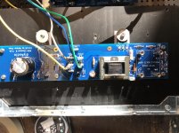
I hooked up one amp board without IPS and put my DMM contacts on v+ and P.gnd and switched on. Voltage started at about 26v and dropped steadily, reaching 24v in about 10 seconds. About then my transformer developed an audible buzz (rather that a hum) and I noticed a faint trail of smoke that appeared to come from the Edcor. I switched it off at that point.
10 secs to reach steady state sounds too fast. 😱
V was still dropping when I switched it off. The smoke from the Edcor was my priority at that point. What’s a good time to steady state as I work on this issue? Thanks.
@jfuquayIf you do all three of these actions before powering up an M2x amp channel card
- completely remove the input stage daughter card
- short the IPS daughter card input (bolt #2) to the IPS daughter card output (bolt #4) with many figure-eight wraps of copper wire
- insert a shorting plug into the RCA input jack, which connects INPUTSIGNAL to GROUND
then you won't force destructive amounts of DC into the Edcor transformer's primary coils.
I strongly recommend that you use your DVM, in "continuity tester" mode, to become absolutely convinced that you've correctly identified bolt 2 and bolt 4. Studying the schematic of the amp card (mother board) below, you can see that only one of the four bolts has electrical continuity to capacitor C0. Eureka and congratulations, you have found bolt #2! Now devise a similar plan to identify bolt #4.
_
Look here 🙂
Thanks. I have not yet wired inputs. Should I do a quickie now or is it OK as is? I’m good on the IPS posts.

Blind listening test results: six different SMD opamps + IPS7
Now that the blind listening test is complete, I am pleased to reveal the identities of the six opamps that were auditioned. If you wish to verify these for yourself, please visit post #4604 and apply the three letter (all capitals) password PIG . There it is.
Member @avdesignguru had no idea what the part-numbers were, he received SOIC chips mounted on DIP-8 adapters, with the chip logo and part number sanded off and then painted over with colored paint. (Testor's enamel for those nostalgic about plastic model cars and airplanes.) Only after his review was complete AND PUBLISHED, am I disclosing which opamp was which.
Here now is his complete review, with opamp part numbers instead of color codes.
---------------------------------------------
Summary of Mark Johnson mystery opamps evaluation
Here is my summary comparison of the 6 mystery opamps and my two reference devices.
For the way that I arrived at the following evaluations, please refer to my previous two posts, #4603 (located here: The diyAudio First Watt M2x) and #4727 (located here: The diyAudio First Watt M2x).
On a number scale of 1 to 5 (5 best) I ranked the following characteristics:
T - Transient Response (a combination of high slew rate and low transient intermodulation distortion)
D - Depth (a combination of low noise and low total harmonic distortion)
B - Balance (a combination of wide bandwidth and flat frequency response)
I'm adding a 4th characteristic, distilled from my original comments:
SF - Smile Factor - do you break out in a grin listening to the music?
In order of preference (note: the first 3 are pretty much interchangable in my preference, they are all very good)
#1 IPS6 - T4, D5, B5, SF5
Smooth, detailed and open with very good imaging. Great sound stage. Studio monitor reference sound.
#2 OPA1612 - T4, D4, B5, SF5
Smooth and detailed with good imaging. Good sound stage. Laid back yet open sound makes extended listening a pleasure. Similar to the Burson V6 Classic.
#3 LM7321 - T5, D4, B5, SF5
Very smooth and clear, with pretty good imaging. Excellent bass instrument and percussive definition. Superior for both male and female vocals. Exciting. Reminds me of the Burson V6 Vivid.
#4 OPA209 - T3, D3, B4, SF4
Balanced overall. Clean but not harsh. OK sound stage. Nothing stands out. No surprises. The Toyota Corolla of opamps.
#5 UA741 (!!!) - T4, D3, B4, SF3
Slightly bright but not harsh. Detailed but with a flat, 2D, sound character. Forward sounding vocals. Has an austere sound with a decidedly soft bass character.
#6 LT1498 - T4, D4, B3, SF3
Clear but with a slight harshness, mostly apparent on female vocals. Appears to lack low bass but that might just be an abundance of highs. Moderate depth to the sound stage but somehow not exciting.
#7 ADA4898 - T2, D2, B3, SF3
Very smooth and non-fatiguing but a bit dull. Slightly veiled and 2-dimensional sounding. Did not handle female vocals well. Soft overall, like late 1970's NAD amplifiers.
#8 LF356 - T2, D3, B2, SF2
Very bright, translating to some apparent detail but unbalanced. Lacks imaging and sound stage depth.
---------------------------------------------
MJ comments --
First of all, a huge THANK YOU to member @avdesignguru for his thorough and no-nonsense review! It will undoubtedly be quite helpful to other M2x owners, who wonder "what's a good candidate to try next?"
I find it amusing to observe the complete and total non-correlation between datasheet spec voltage noise, and subjective listening pleasure. The ADA4898 finished next to last but has an astonishingly low, world-beatingly low, 0.9 nV/rt.Hz noise spec. Yet at the same time the OPA1612 finished next to best (maybe I should say, tied for first place) with an almost-as-astonishing 1.1 nV/rt.Hz noise spec. Low noise is bad, low noise is good, low noise doesn't matter.
"Rail To Rail Inputs and Outputs" also seems not to matter. #3 has them, #2 does not ... but they are tied for best. #6 has them, #8 does not ... but they both finished poorly.
"Fancy Silicon-Germanium Semiconductor Fab Process" also seems not to matter. #1 and #3 are plain old silicon (#1 is plain OOOOOOLD silicon) but #2 is SiGe.
Gain Bandwidth Product seems not to matter much. If you put #1 into MicroCap I think you'll be severly underwhelmed by its simulated GBWP, yet there it sits on top of the heap. Tied for first place is #2 with a GBWP of 40 Megahertz. While finisher #7 has a GBWP of 65 MHz. Go figure.
Open Loop Output Impedance seems not to matter. The ratio (Zout#1 / Zout#2) is greater than ten thousand yet they are tied for first place.
Finally, look at the 5th place finisher. That's a bit of a surprise.
------------------------------
see posts #4547, 4552, 4574
Awesome review avdesignguru! Thank you Mark Johnson for all the efforts in continuing to enhance the listening pleasure of M2X owners!
I, myself, am a very happy camper with the M2X regardless of input cards. But I will definitely try the opamps mentioned in the test and see for myself.
Very grateful!
I, myself, am a very happy camper with the M2X regardless of input cards. But I will definitely try the opamps mentioned in the test and see for myself.
Very grateful!
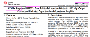
It appears that the LM7321 is a single and will fit nicely on the IPS7?
Cultivate the practice of always downloading and reading the datasheet. Here is what you type: LINK
The top 1/3rd of page 1 of the datasheet is shown below. It tells you that
if you want to plug into the "SINGLE" socket of IPS7, you should buy ___________(part number here)____________________
if you want to plug into the "DUAL" socket of IPS7, you should buy ___________(part number here)____________________
_
Attachments
All these chips are virtual unknowns in the M2x field. Wonder how the original opamps compare (like opa1611 ad744 etc)
I should build the IPS6...darn.
I should build the IPS6...darn.
- Home
- Amplifiers
- Pass Labs
- The diyAudio First Watt M2x