Hi Mike, I'm not worried because I've measured worse for expensive commercial products. Of course also with cheap ones.
I just want to have a perfect symmetrical as possible voltage at the OP Amp and the amplifier to produce also no unnecessary DC offset.
It is a mixture of pedantry and fun in the matter.
Hi Roland,
Having the bipolar rails match perfectly will not change your output offset voltage.
Sorry if this has been asked before, but I have 2 questions.
1. What is the power output of this amp? I saw in head-fi someone mentioned 300-400mW.
2. Any recommendations of a stepped pot/attenuator for gain settings 1k-10k? I supposed this would be a linear instead of a log, am I right?
Thanks.
1) The actual number is dependent on a lot of build variables, but output power is along the lines of 800-1200mW into 20ohms, and you could easily make it more if for some particular reason you are wanting to go deaf with headphones. It will also swing between 12-15v Pk-Pk into whatever headphone you can attach to it. It will literally drive any headphone except a pure electrostatic. (Obviously...)
2) I’m not sure I understand the question. Are you asking about what value potentiometer for the volume control? You want a LOG (also known as Aidio taper) pot/attenuator, and anything between 10k and 50k is fine.
Hi Roland,
Having the bipolar rails match perfectly will not change your output offset voltage.
I mean I once read that an unequal supply voltage affects the DC offset at the output. But that could have been in a different context.
My knowledge in this area is very limited and I haven't been able to do much with my hobby audio in recent years. I will work myself in more there again.
What effects does an unequal supply voltage have in terms of sound and technology?
I was ordering some pcb's with the help of the gerber files that are posted here. The pcb maker mentioned that the bottom side has no soldermask (or it's not in the files). Does anyone encoutered this? I tried to import the files in Kicad to fix the problem but that didn't worked.
1) The actual number is dependent on a lot of build variables, but output power is along the lines of 800-1200mW into 20ohms, and you could easily make it more if for some particular reason you are wanting to go deaf with headphones. It will also swing between 12-15v Pk-Pk into whatever headphone you can attach to it. It will literally drive any headphone except a pure electrostatic. (Obviously...)
2) I’m not sure I understand the question. Are you asking about what value potentiometer for the volume control? You want a LOG (also known as Aidio taper) pot/attenuator, and anything between 10k and 50k is fine.
Hi Jim, thanks for the reply on the output power.
2) Sorry for the confusion, I meant placing a stepped attenuator in replacing r4 & r8 or r1 & r12. Just to be able to play with different gain settings
I was ordering some pcb's with the help of the gerber files that are posted here. The pcb maker mentioned that the bottom side has no soldermask (or it's not in the files). Does anyone encoutered this? I tried to import the files in Kicad to fix the problem but that didn't worked.
Hi, yes i had the same problem. All i did was make a duplicate of the soldermask file. and just indicate one for top and one for bottom.
I took a look at the Sparkos regulators last night based on the thread here and have a simple question as it is not obvious from their data sheet: are these drop in replacements for the 7815/19s (i.e.: pin for pin and resistor/bypass caps) ? The data sheet discusses recommendations for certain types of caps to be attached close to the regulators.
The other question is: is it worth the hassle/cost? I can say for sure that their dual-discrete opamps are in the Whammy. The only discrete I found at a similar level of quality are the Burson ones, but at that point its a matter of taste - which is half of why I am personally obsessed with this stuff!
The other question is: is it worth the hassle/cost? I can say for sure that their dual-discrete opamps are in the Whammy. The only discrete I found at a similar level of quality are the Burson ones, but at that point its a matter of taste - which is half of why I am personally obsessed with this stuff!
@6L6
Thanks for your help,
as I said, my Motorola MC7815CV and MC7915CV come from such a campaign in which we selected over 200 pairs, but that was almost 20 years ago ...
Next time I will order and measure a few from Mouser.
I will test that with the different LEDs soon and will post the result here. Has anyone tested how large the forward voltage spread of a type is?
I had already looked at the voltage regulators from Sparkos, but I would first test an external board with LM317 / 337 or the SUPER REGULATOR power supply from the DIY audio store.
But I will ask Sparkos if they are suitable for this large voltage difference. Maybe I'll test the parts ...
I am not a big friend of interventions to remove DC offset, so the coupling capacitors should also be removed. For me it is always the best solution to prevent a problem than to have to solve it afterwards. However, I am also a very lazy person...
Thanks for the tip,
the LM317 / 337 could also be placed directly on the board with a small circuit, but I will first order and try out other 78/7915 and LEDs.
Then I want to test whether a "better" power supply really has an effect and makes the Whammy even "quieter", or not
I mean I once read that an unequal supply voltage affects the DC offset at the output. But that could have been in a different context.
My knowledge in this area is very limited and I haven't been able to do much with my hobby audio in recent years. I will work myself in more there again.
What effects does an unequal supply voltage have in terms of sound and technology?
The sound will not be affected by unequal power supply voltage rails.
Consider a perfect sine wave being amplified. As the waveform moves into the positive range that amplified output voltage comes from the positive power supply rail. As the wave goes negative the output comes from the negative supply rail. When you increase the level of the sine wave feeding the amplifier the output also increases but it can only increase to a certain point because the amplifier can't deliver more voltage swing than the power supply can provide. So with a + and - 16 volts supply the amplifier will output a little less than + and - 16 volts peak as it's maximum. If you increase the input level more the sine waves will begin to flat top and this is called clipping. With higher power supply voltages, let's say + and - 18 volts, you can drive the amplifier higher and get a output voltage swing that starts to clip at a little less than the + and - 18 volts output voltage swing. But if your positive rail is 16 volts and your negative rail -18 volts the positive side of the waveform will clip first as the level is increased and the negative side will hold it's shape as the level is increased up until it reaches near -18 volts.
So asymmetric power supply voltages cause asymmetric clipping of the waveform but only when we drive the amplifier to clipping. We never want to drive these headphone amplifiers that hard anyway so clipping is not going to be an issue.
Some people use the Whammy as a preamp for amplifiers that require an output voltage swing near + and - 24 volts. They use 24 volt voltage regulators and an op amp that can handle +/- 24 volts. There are very few op amps that can handle that voltage.
I took a look at the Sparkos regulators last night based on the thread here and have a simple question as it is not obvious from their data sheet: are these drop in replacements for the 7815/19s (i.e.: pin for pin and resistor/bypass caps) ? The data sheet discusses recommendations for certain types of caps to be attached close to the regulators.
The other question is: is it worth the hassle/cost? I can say for sure that their dual-discrete opamps are in the Whammy. The only discrete I found at a similar level of quality are the Burson ones, but at that point its a matter of taste - which is half of why I am personally obsessed with this stuff!
From what I have heard so far about the parts of this company, they should work at a high level.
In the next few weeks I will test different power supplies in the Whammy, whether or how they have an acoustic effect, e.g. SUPER REGULATOR but also really bad old 78/7915.
Then you can at least estimate whether the Sparkos regulators are worth trying.
The Sparkos regulators are available in all variants to replace other regulators.
Scroll down on the page far, there are sketches on the right with the overview.
Sparkos Labs, Inc. audio power supply discrete voltage regulators
The sound will not be affected by unequal power supply voltage rails.
Consider a perfect sine wave being amplified. As the waveform moves into the positive range that amplified output voltage comes from the positive power supply rail. As the wave goes negative the output comes from the negative supply rail. When you increase the level of the sine wave feeding the amplifier the output also increases but it can only increase to a certain point because the amplifier can't deliver more voltage swing than the power supply can provide. So with a + and - 16 volts supply the amplifier will output a little less than + and - 16 volts peak as it's maximum. If you increase the input level more the sine waves will begin to flat top and this is called clipping. With higher power supply voltages, let's say + and - 18 volts, you can drive the amplifier higher and get a output voltage swing that starts to clip at a little less than the + and - 18 volts output voltage swing. But if your positive rail is 16 volts and your negative rail -18 volts the positive side of the waveform will clip first as the level is increased and the negative side will hold it's shape as the level is increased up until it reaches near -18 volts.
So asymmetric power supply voltages cause asymmetric clipping of the waveform but only when we drive the amplifier to clipping. We never want to drive these headphone amplifiers that hard anyway so clipping is not going to be an issue.
Thanks for the explanation, that is very plausible.
I had read again and again how important a clean and equal supply voltage on the + and - rails is, but without explanation for the "same" +/- voltage in the supply.
20 years ago I spent some time in Germany with a few tuners. One point in her work was to replace the cheap voltage regulators with high-quality and selected pairs. The result was clear in terms of sound, but I'm not sure whether they also listened to unselected voltage regulators ...
Some people use the Whammy as a preamp for amplifiers that require an output voltage swing near + and - 24 volts. They use 24 volt voltage regulators and an op amp that can handle +/- 24 volts. There are very few op amps that can handle that voltage.
This is a good start for something that burns under my nails.
I have a headphone amplifier from a German manufacturer on my table. I just wanted to listen to it for a few weeks and then sell it again. That was over 2 years ago.
The output stages are operated directly on the unregulated voltage of + / - 33.8v (measured), the OP amps on regulated + / - 18v.
Would something like that be possible with Whammy?
20 years ago I spent some time in Germany with a few tuners. One point in her work was to replace the cheap voltage regulators with high-quality and selected pairs. The result was clear in terms of sound, but I'm not sure whether they also listened to unselected voltage regulators ...
Roland,
Good regulators and power supplies do make a big improvement. I've used the Jung/Didden super regulators in lots of equipment. I've even modified broadcast transmitters and analog microwave links with them and had the best sounding radio stations on the dial. Low noise is important but what else is really important is the power supplies' low impedance at audio frequencies. Remember that every sharp crack of a snare drum has to come from your power supply rails and if the power supply can't respond fast and keep it's composure then the audio will suffer. The super regulators with the remote sense lines are great devices and the magazine articles about them explain very well about power supply performance.
Mike
Mike, you're making me more and more curious.
Can you tell me for what I need a regulated supply for a OP Amp?
If I only use an over-dimensioned transformer with 2 x 10V and 5-7 watts for the OP amp, so that I can build the Wahmmy CRCRC power supply again and bias the power supply with a 2k resistor between + / - directly after the diodes, would that work?
Voltage regulation for the op amp brings the noise floor way down and it protects your OP Amp from over voltage. I'm not envisioning what you are considering with the 2K resistors. Lots of things would work but you need reasonable filtering which would ideally include CRC separate from the output stage at the least.
Ok, protection is a problem without a voltage regulator. I do not yet understand that with the increased noise without voltage regulator. I still have to deal with this topic.Voltage regulation for the op amp brings the noise floor way down and it protects your OP Amp from over voltage. I'm not envisioning what you are considering with the 2K resistors. Lots of things would work but you need reasonable filtering which would ideally include CRC separate from the output stage at the least.
If so, I would use separate transformers and CRCRC filtering for the power amplifier and OP amp.
Since the OP Amp does not really burden the transformer, I would load the transformer with the 2K resistance.
I do not yet understand that with the increased noise without voltage regulator. I still have to deal with this topic.
Voltage regulation by nature reduces voltage ripple and droop, and ripple can introduce noise into an op amp.
Last edited:
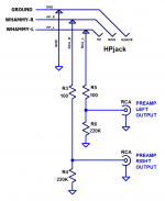
I received a Private Message from a member, who is considering building a modified WHAMMY that includes a switched headphone jack and "preamp output" RCA connectors. S/he asked a bunch of questions which, in my opinion, are best discussed in the Forum where everybody can participate and learn.
The builder is thinking about using an arrangement similar to the one used by the Noir headphone amp from the DIYA Store; schematic below.
In this arrangement, the switched headphone jack (a Neutrik NMJ6HFD2) connects the WHAMMY outputs to the RCA jacks if, and only if, there is no headphone plug inserted. However, when a headphone plug IS inserted, the WHAMMY outputs are disconnected from the RCA jacks; the signal path is interrupted.
I'm sure the builder would love to have the opinions of other Forum members, about this sort of idea. Perhaps including, but certainly not limited to,
Thank you to everyone!
The builder is thinking about using an arrangement similar to the one used by the Noir headphone amp from the DIYA Store; schematic below.
In this arrangement, the switched headphone jack (a Neutrik NMJ6HFD2) connects the WHAMMY outputs to the RCA jacks if, and only if, there is no headphone plug inserted. However, when a headphone plug IS inserted, the WHAMMY outputs are disconnected from the RCA jacks; the signal path is interrupted.
I'm sure the builder would love to have the opinions of other Forum members, about this sort of idea. Perhaps including, but certainly not limited to,
- Is this a reasonable idea? Does it have hidden (or obvious!) flaws?
- Are the 100 ohm resistors really necessary? Or can they be eliminated? What's the optimum resistance value?
- Are the 220K ohm resistors really necessary? What's the optimum resistance value?
- What are some other options for switching headphone jack functions? Are they preferable to this one?
Thank you to everyone!
Attachments
- Home
- Amplifiers
- Pass Labs
- "WHAMMY" Pass DIY headphone amp guide