@Russell.....
now I'm sure which trace is that, but I'm not telling
feel free to rotate pcb and un-make that wiring mess

.....
I prefer rotation, though, if you insist - I can see later which trace needs cutting, but be aware that I can't be sure that it will cure crosstalk 100%
now I'm sure which trace is that, but I'm not telling
feel free to rotate pcb and un-make that wiring mess
Thank you for the suggestions. Neat coupler ideas.
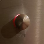
I'll switch selector and pot. The front face has LED holes next to the selector. But no light show. I might add power led, because I keep having to look at switch to check on, off.
Forgot to say, signal, pot wires are from a broken hdmi cable, inspired by 6L6.
I couldn't resist.
Attachments
24h rotation, silly ...... and you can't tell that I didn't told you before
reason is that you bundled all those wires together, there must be crosstalk, especially with unused inputs routed to GND (muted)
now, you have solution - either cut GND trace which is connected to relays to mute unused inputs , or rotate pcb 90deg CCW, to be oriented as I planned it to be - to have properly short wires from RCAs to input pads, so being properly separated
I prefer rotation, though, if you insist - I can see later which trace needs cutting, but be aware that I can't be sure that it will cure crosstalk 100%

Then the board will have to be reoriented. If this cures it, great. A lot I dont understand, what I dont get is why "bleed through" only occurs between two inputs that something plugged into them, then either other item bleeds through, or if other item is off, signal on active input bleeds through to inactive (unselected) input. Maybe this is typical? Just seems odd, to me anyway that bleed through only occurs between inputs that something is plugged into. Seems like it would bleed through to even unused (nothing plugged into) inputs as well.
I will reorient, but I dont see why this would help, (but lots I dont understand) have longer leads on other preamps without cross talk. That said, there is lots here I probably dont understand.
What are the paths this signal is taking? Sounds like it may be through grounds somehow? Sounds like new boards have facility to remove ground to relays if I understood correctly? Was there a similar bleed through noticed as developed? Obviously I have some learning to do.
Russellc
Last edited:
reason is that you bundled all those wires together, there must be crosstalk, especially with unused inputs routed to GND (mute)
Just to make sure you understand me, bleed through only occurs when two different sources are plugged into preamp, and only between those two. All other positions (with no source plugged into them) are quiet, no bleed through.
If only one source attached to preamp, all other positions are dead quiet if selector is turned to them.
Russellc
Would cutting ground help this with caveat given in above post that no bleed through happens to inputs without a source plugged into them? Dont want to cut ground if not, and will wait for rewire before doing that. Was this particular board having tendency to bleed through without short wires?
Russellc
Russellc
When it hits the store, I will build revised kit and install, hopefully there is an option without Iron, as I have a pair but I guess I will need yet another pair when I revisit F6.
Maybe store will have an option for cinemag iron with kit? Otherwise maybe I better get an order in for when they start back up.
Russellc
Maybe store will have an option for cinemag iron with kit? Otherwise maybe I better get an order in for when they start back up.
Russellc
Russel, I have absolutelly same arrangement of grounds, both signal and muting, and relays in my Iron Pumpkin and - when properly oriented and wired, as I made them , everything is dead silent regarding crosstalk
remember that I didn't made sole one Iron Pre with these pcbs, nor I intend to - they're exclusively made for Boyz Store; frankly, I didn't even need to make my own specimens in testing purposes, simply because all sub-blocks are previously made and tested by Mighty Moi, in some other builds
so, cut that trace and see will it help in your specific case - you have your own unique combination of circumstances - bunched signal wires, sources of unknown Rout etc. so I can't give you exact recipe, as I tried to make with my specific arrangement for muting unused inputs along with advice how to arrange pcb in case
or re-orient pcbs and see is new neat wiring arrangement going to help
feel free to take more than 24hours for that ......")
remember that I didn't made sole one Iron Pre with these pcbs, nor I intend to - they're exclusively made for Boyz Store; frankly, I didn't even need to make my own specimens in testing purposes, simply because all sub-blocks are previously made and tested by Mighty Moi, in some other builds
so, cut that trace and see will it help in your specific case - you have your own unique combination of circumstances - bunched signal wires, sources of unknown Rout etc. so I can't give you exact recipe, as I tried to make with my specific arrangement for muting unused inputs along with advice how to arrange pcb in case
or re-orient pcbs and see is new neat wiring arrangement going to help
feel free to take more than 24hours for that ......
take in account that signal gnd for inputs is one trace , going to central GND point, while muting gnd trace is second, different trace going to central GND point, and these two are almost half pcb width appart
crosstalk is phenomenon easiest explained as one antenna talking to second one
you made looong input wires, all bundled together, thus enormously increasing physical dimensions of emitting and receiving antennas
practically - one antenna is starting at source RCA, including interconnects, then preamp input RCA, then wiring from them to pcb, then all signal traces on pcb, including GND traces
and , if Rout of active source is highish, that input is even more prone to crosstalk, Rout of source acting as I/V conversion impedance
you said you have Samsung and Dragonfly; first one is certainly drek, regarding Rout (I have one, so...) while second one is small enough that I can't count too much on it's Cojones
so ......... hope you get it now
edit: in definitive pcb iterations, shown up by rthatcher, there is jumper included in that muting GND trace, me caring that Greedy Boyz are having all options, besides various gain and various Iron
Last edited:
Ok, total rewire and board reorientation begins. Should be just in time for extenders to arrive. The existing wires on RCA jacks will be left in place on board end, but removed from said jacks, wires shortend and reattached to the RCA jacks as board reorient requires.
If that doesnt solve it, will try trace cut.
Russellc
If that doesnt solve it, will try trace cut.
Russellc
that xformer is working , but 20-30VA is gong to be better
I resume that present one is just enough and you'll not hear difference with bigger one (tnx to Good Gemini reg), but having enough instead is better for sleep
enjoy
edit: swap places of input selector and pot
fix pcb all way right, behind moved sellector switch
then you'll have free place to move volume pot all the way back , in-line with pcb pot pads, so having shortest possible wires
use extending shaft and coupler ; for front plate bushing use face of old pot , for extending shaft look in local metal store, for coupler you can buy piece of rubber hose (5mm ID) for gasoline, look in local automotive parts store
zip ties are good enough to secure coupler
see here : Iron Pre | Zen Mod Blog

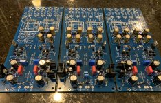
Where can one get that nice little relay board? Very nice and tidy. I would love Iron Pre Broken up into 3 boards, Power supply, buffer, Iron part...talk about greedy.
Russellc
Last edited:
I hardly recognized it - it was my board, but long ago abandoned
having it all in blocks is not always best solution........ all on one pcb is much cleaner and when incorporated in proper arrangement with everything else in case, it results in better sound
same as proper reg isn't just schematic, pcb design of it being of equal importance, it applies pretty much on everything else
I am sure it's here somewhere in the 900+ entries but obviously well hidden.
Can you provide recommended value for regular volume pot?
Much appreciated.
10Klog to 25Klog; some call it Audio-taper
lower if sources are having proper Cojones ( Rout lower) , higher if you have weaklings among sources
Now I need cinemags.
Whoops I thought for some reason that this needed 25 to 50 K. I'm sure these values obviously work as I've been using 25K. Since I'm rewiring parts of this it would be easy to put 100k to 250 k if would be better. Inputs have sissy drive on this (TV) particular set up.
Russellc
Russellc
24h rotation, silly ...... and you can't tell that I didn't told you before
reason is that you bundled all those wires together, there must be crosstalk, especially with unused inputs routed to GND (muted)
now, you have solution - either cut GND trace which is connected to relays to mute unused inputs , or rotate pcb 90deg CCW, to be oriented as I planned it to be - to have properly short wires from RCAs to input pads, so being properly separated
I prefer rotation, though, if you insist - I can see later which trace needs cutting, but be aware that I can't be sure that it will cure crosstalk 100%
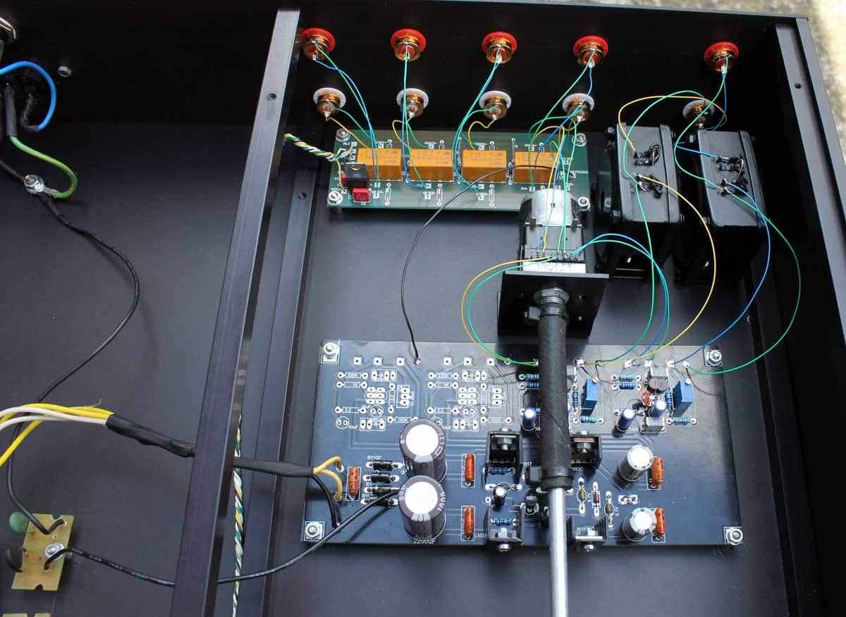
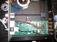
OK, a little rewiring, as far as can get without extension kits to move selector and volume pot to rear location.
I need a wider box to use the layout I want with front plate switching the way I wanted it. When Iron pre hits store, that build will use a wider one
for sure.
I dont like where selector ends up, to close to RCA jacks, but front panel already drilled.
Oh well, at least board closer to correct orientation. Getting ready to try it as is for now, more after extenders get here. The long lines to volume pot are still problem, (until extenders arrive) Then there is selector pot. Dont know if it is more problematic as they only switch relays?
That,s it for now.
Russellc
Attachments
![IMG_4796[1].JPG](/community/data/attachments/761/761288-c112e4cc2379633edc5e9e57d348b77d.jpg)
What's wrong with .....
....this arrangement, boy?
regarding selector switch, as you said - it is just energizing relays, so you can situate it in next room , as far as I'm concerned
regarding that L bracket, shown in between pcb and RCAs, I'm really not getting purpose of that
....this arrangement, boy?
regarding selector switch, as you said - it is just energizing relays, so you can situate it in next room , as far as I'm concerned
regarding that L bracket, shown in between pcb and RCAs, I'm really not getting purpose of that
Attachments
- Home
- Amplifiers
- Pass Labs
- What's wrong with the kiss, boy?