Thanks ZM!
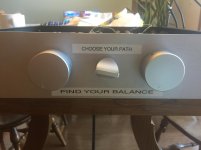
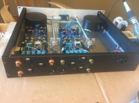
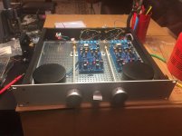
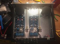
A few pics of progress. All wiring done and fairly tidy. I need to troubleshoot the twister tomorrow. All relays worked fine when individually activated, but they're behaving funny. I think I may have mis-crimped the 14-pin IDCs. I'll beep test them.
Then... I need to take the front panel to have LED holes done and get some artwork... the label maker is temporary 😀
Lighting is not super in the shots.


Thanks, Dennis!
Hi ZM - Well, I have been bashing my head cussing
  and a few other things.
So... just last tiny things until success.
First - good news. Nothing wrong with my 14-pin home-made connectors. After doing lots and lots of beeps. Everything is good except my ability to hear relay clicks. With make-before-break switch it was too hard - so I thought relays were not clicking. They are fine...
EXCEPT... for one silly relay (or two) on only one channel.
With the selector in position 2 or 3 both relays K2 and K3 are firing. ~24V across D8 and D9. I lifted board from mount gently to examine underside for bridges etc (pic attached). Apologies for challenging quality. I did not want to unsolder all inputs / outputs / pot etc. So, I tried to get a good shot.
I have closely examined under magnification top and bottom. I tried to trace schematic back to power prior to D8 / D9 to see where issue may be. It must be a bridge or something b/c the other channel operates perfectly. When I was checking each input one by one... no problem. Input 2 works... Input 3 works.
They just work together. DOH! I should have done full 100% check before installing the board and soldering itsy bitsy wires.
Any help is appreciated for where to look.
Edited to add - I originally thought it may be a short within the 14-pin connector. I eliminated that possibility along with anything at the twister by activating the relay with a jumper only between the two pins on the header.

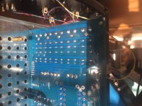
Hi ZM - Well, I have been bashing my head
 cussing
  and a few other things.
So... just last tiny things until success.
First - good news. Nothing wrong with my 14-pin home-made connectors. After doing lots and lots of beeps. Everything is good except my ability to hear relay clicks. With make-before-break switch it was too hard - so I thought relays were not clicking. They are fine...
EXCEPT... for one silly relay (or two) on only one channel.
With the selector in position 2 or 3 both relays K2 and K3 are firing. ~24V across D8 and D9. I lifted board from mount gently to examine underside for bridges etc (pic attached). Apologies for challenging quality. I did not want to unsolder all inputs / outputs / pot etc. So, I tried to get a good shot.
I have closely examined under magnification top and bottom. I tried to trace schematic back to power prior to D8 / D9 to see where issue may be. It must be a bridge or something b/c the other channel operates perfectly. When I was checking each input one by one... no problem. Input 2 works... Input 3 works.
They just work together. DOH! I should have done full 100% check before installing the board and soldering itsy bitsy wires.
Any help is appreciated for where to look.
Edited to add - I originally thought it may be a short within the 14-pin connector. I eliminated that possibility along with anything at the twister by activating the relay with a jumper only between the two pins on the header.


Last edited:
considering that channel pcbs are identical, for ooompteeenth time is confirmed that pcb design is OK
for start - borrow flat cable from good channel and try on faulty one
besides , you can check is it pcb or is it cable in other way - use short wire and pair adequate pins directly on channel IDC connector, logically connecting :
+ labeled pair of pins with 1 labeled pair of pins , for relay/input No.1
+ labeled pair of pins with 2 labeled pair of pins , for relay/input No.2
+ labeled pair of pins with 3 labeled pair of pins , for relay/input No.3
+ labeled pair of pins with 4 labeled pair of pins , for relay/input No.4
+ labeled pair of pins with 5 labeled pair of pins , for relay/input No.5
also- you can check twister itself, simply replacing places of two cables on twister itself
I can bet and hope that you buggered flat cable, and that would be cheapest mistake
....
Edited to add - I originally thought it may be a short within the 14-pin connector. I eliminated that possibility along with anything at the twister by activating the relay with a jumper only between the two pins on the header.

if you try that routine , exactly as I wrote in previous reply, how many of them are operating?
beep test - all 5 diode anodes must beep together, being attached to "-" labeled IDC pin pair and neg relay supply
beep test , each diode cathode separately must beep to it's own pair of IDC pins
also , with IDC cable removed, you can confirm each relay coil Rdc , measuring across paired diode , in proper orientation that diode is not influencing reading , red probe at cathode
Sorry for delay - I had to go to an appointment.
PCBs are perfect. I know there has to be a short / blob something... somewhere. I just can't find the silly problem after beeping my brains out.
100% of relays operate. The only issue is that K2 and K3 activate simultaneously whether switch is in Pos 2 or 3 (or if I manually activate either K2 or K3 with jumper at header pins.
Confirmed.
All ok except for 2 and 3 which have the short. I just can't find the short. Can a short be between the relays??? I beep tested pins on header also just to confirm. No problem there.
All tests done with cable removed. I want to confirm I did this properly b/c I am not sure I understand even after a Google search and checking the spec sheet for the relay. Is Rdc the resistance across the diode? All are showing open circuit, but that should be expected. Should I do this with power applied and switch selected to one of those positions? Sorry for silly question. Just never want to waste your time doing an improper measurement.
considering that channel pcbs are identical, for ooompteeenth time is confirmed that pcb design is OK
PCBs are perfect. I know there has to be a short / blob something... somewhere. I just can't find the silly problem after beeping my brains out.

if you try that routine , exactly as I wrote in previous reply, how many of them are operating?
100% of relays operate. The only issue is that K2 and K3 activate simultaneously whether switch is in Pos 2 or 3 (or if I manually activate either K2 or K3 with jumper at header pins.
beep test - all 5 diode anodes must beep together, being attached to "-" labeled IDC pin pair and neg relay supply
Confirmed.
beep test , each diode cathode separately must beep to it's own pair of IDC pins
All ok except for 2 and 3 which have the short. I just can't find the short. Can a short be between the relays??? I beep tested pins on header also just to confirm. No problem there.
also , with IDC cable removed, you can confirm each relay coil Rdc , measuring across paired diode , in proper orientation that diode is not influencing reading , red probe at cathode
All tests done with cable removed. I want to confirm I did this properly b/c I am not sure I understand even after a Google search and checking the spec sheet for the relay. Is Rdc the resistance across the diode? All are showing open circuit, but that should be expected. Should I do this with power applied and switch selected to one of those positions? Sorry for silly question. Just never want to waste your time doing an improper measurement.
measurement across diodes must show Rdc of coils, simply bcs diodes are in parallel with coils
from top of my head - for 24V relays, current is (say roughly) 15mA - which means 24V/15mA..... you can expect readout of some 1K6
so, relays 2 and 3 are actuating at same time, regardless is twister on position 2 or 3?
if you can beep between pins 2 and 3 on IDC on channel pcb, culprit is on pcb
as I said - try swapping cables between pcbs, then cables on twister , pretty much anything I wrote in sum , methodically you'll locate where problem is - on channel pcb itself, or in cable or in twister
easy as that; first locate where problem is, then we can proceed further to find a cure
.....
100% of relays operate. The only issue is that K2 and K3 activate simultaneously whether switch is in Pos 2 or 3 (or if I manually activate either K2 or K3 with jumper at header pins.
......
.......
aha, I just reread
in that case , confirm beep between pins 2 and cathode of diode (D8) at relay 2
do the same with pins 3 and cathode of diode (D9) at relay 3
by logic, there must be also beep between these two cathodes, same as between pins 2 and 3
that's the logic.... if anything is different, then Gremlins are in case and power and there is hardly anything I can do against them 🙂
use good light and lens if needed , and see is there copper whisker between traces going from IDC to D8 and D9 cathodes
Hi ZM -
I think I am understanding, but I want to be 100% certain and capture all recommendations. There must be a whisker somewhere... or something odd, but I just cannot figure it out.
1) Understood now re: Rdc. All "good" inputs at ~2k7 to 2k8. Input 2 and 3 measure 1k4. It seems something may be in parallel??? However, your estimate is closer to the misbehaving ones.
2) Confirming beep between pin2 and cathode of D8. Same for D9 and pin 3. However - just to confirm I was clear - there is also beep between pin 2 and D9 and pin 3 and D8. That is the bad part. That is what I just cannot figure out... where is this mysterious little whisker or gremlin making my life crazy I have been over and over the board.
I think I am understanding, but I want to be 100% certain and capture all recommendations. There must be a whisker somewhere... or something odd, but I just cannot figure it out.
1) Understood now re: Rdc. All "good" inputs at ~2k7 to 2k8. Input 2 and 3 measure 1k4. It seems something may be in parallel??? However, your estimate is closer to the misbehaving ones.
2) Confirming beep between pin2 and cathode of D8. Same for D9 and pin 3. However - just to confirm I was clear - there is also beep between pin 2 and D9 and pin 3 and D8. That is the bad part. That is what I just cannot figure out... where is this mysterious little whisker or gremlin making my life crazy
 I have been over and over the board.
Can diodes fail "closed"? That's my last hair-pulling idea. By checking the schematic, if either D8 or D9 failed "closed" - That would (if one diode was working) allow the relays to latch, but cause the short between the pins and thus closing both.
Did I interpret that properly?
If so, I will very delicately see if I can determine which may be faulty and replace. I think I can do it without damaging all my itsty bitsy wires.
Edited to add - I did a bit of internet searching. Time to put on my "big boy pants", and see if I got this right. It seems diodes can fail closed... perhaps that's it. Time to do some delicate surgery....
Last edited:
For those playing the home game... that was it. Bad D8 or D9. I am still not perfectly versed in how to check to ensure proper function of a diode. They both tested "open" or OL for a simple resistance check when removed, but my guess is that when under voltage one of them passed current "prematurely" or something... or I could have cleaned up a bad joint. It's unlikely, but I'm willing to admit there was a hair of something somewhere.
So... it's all 100% running as intended. A bit more to make it pretty, and it's done.
Thanks as always, ZM!!! 😀
So... it's all 100% running as intended. A bit more to make it pretty, and it's done.
Thanks as always, ZM!!! 😀

LOL!
Well... today was my day... then it wasn't. Boy am I a dodo. I've now fried the PSU section for the relays on this board. R1 and R3 up in smoke. I was a complete dodo and unplugged my soldering iron instead of the pre-amp. As I was re-assembling the unit - I brushed the body of the pot up against the back side of M3.
I have to put it aside for today ... too much for my heart to take. I had it 100% working... then I killed the recovering patient.
I have to laugh. I learn as I goof... so there's that.

R1 and R3 are in positive rail shunt reg, more precisely - around input CCS in positive rail
check BD and small bjt , diodes in bridge and practically everything in positive rail
first for shorts and if anything looks fishy, check more thoroughly
so, again, R1 and R3 are not having anything with relay PSU section; if relays are silent and you deduced that's something connected, I can bet that diodes in bridge are Dodo, thus no relays action
regarding your ooriginal problem - relays 2 and 3 being activated in same time - you practically confirmed everything I wrote , with your beeps
though , there is no way that R8 and R9 being open are having anything with that; you had short somewhere, and you obviously cured it while fiddling with diodes; them being funny is either coincidence or maybe sign that you ooked their orientation, frying them in first energizing ..... which is easy - you need just 200mA for that
Last edited:
Thanks, ZM and Dennis!
I will report more information when I get back to the board. Honestly, after having it all 100% working and then making such a goof... I had to walk away for a while.
I'll send some photos later, but I smoked a lot of parts. Just silly.... .
.
Oh well, this is how we learn to not be silly moving on. I built it... I can fix it... tomorrow. 😀
I will report more information when I get back to the board. Honestly, after having it all 100% working and then making such a goof... I had to walk away for a while.
I'll send some photos later, but I smoked a lot of parts. Just silly....
 .
. Oh well, this is how we learn to not be silly moving on. I built it... I can fix it... tomorrow. 😀
Tunes are still fantastic. Kudos ZM.
I added input #3. RCA connectors were different than previous 2. Source #3 is a Rotel rcd 855. Since Russellc and I have the 2016 board, I wanted to check if I have any of his symptoms. Answer is no. No bleed through of one source into another. There is no difference to my ear between unwired and wired but silent input when unselected input is playing. Both dead quiet, even at full volume.
The only time there were gremlins was when interconnects were not making good contact with the input terminals.
My respect for Pioneer SP-FS51-LR speakers has jumped. Acurus power amp 200x3 is also shining.
Last edited:
Hi ZM -
Taking a look at the board under magnification this morning (pic attached) - I only see damage to the rectification section (D2 specifically met a particularly grisly death) along with R3 and R4. I am fairly certain I saw a puff come from R1 although it looks okay.
So, the current idea is to replace all the 4004s (D1-D4) just for safety. Replace R1, R3, and R4.
However, if R1, R3, and R4 are up in smoke - it would stand to reason that T1 got bitten wouldn't it?
Short version - I do not mind soldering and desoldering to fix my goof. However, it seems like a very small number of parts that physically look damaged. What other parts would be a smart idea to replace for caution. Fortunately, I have a lot of extras of everything, I believe.
I will get this done properly sometime this century
With thanks again!
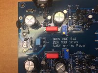
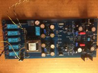
Edited - Re-upload picture. Added full board
Taking a look at the board under magnification this morning (pic attached) - I only see damage to the rectification section (D2 specifically met a particularly grisly death) along with R3 and R4. I am fairly certain I saw a puff come from R1 although it looks okay.
So, the current idea is to replace all the 4004s (D1-D4) just for safety. Replace R1, R3, and R4.
However, if R1, R3, and R4 are up in smoke - it would stand to reason that T1 got bitten wouldn't it?
Short version - I do not mind soldering and desoldering to fix my goof. However, it seems like a very small number of parts that physically look damaged. What other parts would be a smart idea to replace for caution. Fortunately, I have a lot of extras of everything, I believe.
I will get this done properly sometime this century

With thanks again!


Edited - Re-upload picture. Added full board
Last edited:
replace what's obviously Dodo, then use your Beep! on parts, especially BD and BC and diodes
compare beep nature with good channel
don't rush, that's the main thing
compare beep nature with good channel
don't rush, that's the main thing
- Home
- Amplifiers
- Pass Labs
- What's wrong with the kiss, boy?