Both Douglas Self's book, and Bob Cordell's book, say that when you compare the two options
then option B measures better. Lower THD at 20 kHz.
Which one gives a subjectively preferable listening experience? The answer probably varies from one listener to the next.
In a Class A output stage, I personally don't dare run an output transistor at a DC bias current greater than about (35 / Vrail). So for a rail voltage of +23V as in the stock M2, I don't dare run an output transistor at a dc bias current greater than 1.5 amps. Other designers may be bolder than I am.
A. 1 single output device, with source resistor, biased at "I" amperes
B. N parallel output devices, each with its own source resistor, each one biased at "(I / N)" amperes
B. N parallel output devices, each with its own source resistor, each one biased at "(I / N)" amperes
then option B measures better. Lower THD at 20 kHz.
Which one gives a subjectively preferable listening experience? The answer probably varies from one listener to the next.
In a Class A output stage, I personally don't dare run an output transistor at a DC bias current greater than about (35 / Vrail). So for a rail voltage of +23V as in the stock M2, I don't dare run an output transistor at a dc bias current greater than 1.5 amps. Other designers may be bolder than I am.
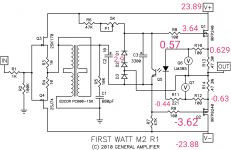
For those who haven't seen it yet, diyAudio's own Scott Wurcer has measured an Edcor PC600-15K as used in the First Watt M2, and built a SPICE simulation model that fits his measurements. So, if anybody was planning to put M2 into LTSPICE, your task just got a little easier.
Indeed, a lot easier ! (Many thanks Scott)
I haven't seen anyone post their LTSpice model so here is my attempt. (use at your own risk, I'm no EE.

The way to connect the transformer with 11x gain gives significantly better THD. I'm wondering why Nelson didn't do it like this in the first place ?
Attachments
The way to connect the transformer with 11x gain gives significantly better THD. I'm wondering why Nelson didn't do it like this in the first place ?
Sorry my bad, the one with less gain gives lower THD (I had messed up with other parameters)
Interestingly, increasing the bias does not seem to result in better figures.. so again... Nelson made it right from the start
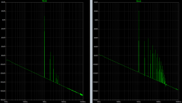
Below is THD @1W and @15W
Distortion is mainly 2nd Harmonics @1W but seems to get slightly "odd ordered" at higher power (H2<H3, H4<H5, etc..).
Attachments
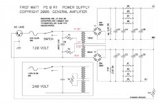
Greetings to fellow M2 amplifier builders. I thought I would mention here, that after doing a bunch of lab experiments, I have decided to substitute a new and different part number in the power supply of my M2. I'm using the same schematic as the First Watt class A power supply (shown below), just with a different part instead of the CL60. I'm not saying there's anything wrong with the design below using the CL60. I just like the new part a lot more. It is my personal preference, with which you are free to disagree. Here is a link, scroll down to post #17 for the nitty gritty details.
Mark Johnson
Mark Johnson
Attachments
Another one is alive...
Hi all,
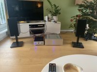
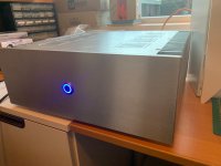
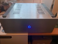
Another M2 is alive! Tea-Bag boards, no space for the rectifier boards so used bridges. Case from aliexpress. It is driven by my (also diy) DCG3. Heatsinks get warm but not too hot; I am able to touch indefinitely and measured a tad above 40 degrees Celsius.
Amp is dead quiet on the shown Elac speakers.
Happy!
Steef
Hi all,
Another M2 is alive! Tea-Bag boards, no space for the rectifier boards so used bridges. Case from aliexpress. It is driven by my (also diy) DCG3. Heatsinks get warm but not too hot; I am able to touch indefinitely and measured a tad above 40 degrees Celsius.
Amp is dead quiet on the shown Elac speakers.
Happy!
Steef
Attachments
Hi all,
Another M2 is alive! Tea-Bag boards, no space for the rectifier boards so used bridges. Case from aliexpress. It is driven by my (also diy) DCG3. Heatsinks get warm but not too hot; I am able to touch indefinitely and measured a tad above 40 degrees Celsius.
Amp is dead quiet on the shown Elac speakers.
Happy!
Steef
Nice neat build, looks great! Enjoy your M2!
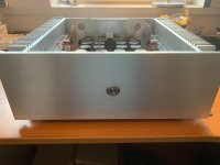
I finally finished my M2C. Tea-bag’s boards are really nice.
I built it with the Cap-Mx boards, one for each channel and dual transformers. The transformers are 20v 400VA, so I can get 23VDC from the Cap-Mx boards. Thanks for the great design and contributions making these available.
I built the amp using the BLASPHEMOUS HERESY offset. I think I my have used a single turn variable resistor, because it is very sensitive, but I was still able to get the offset dialed in with little nudges.
The amp is nice and quiet, with no hum. It also works well with my VTA SP14. I now have more flexibility adjusting the volume and the 100k input impedance on the M2C matches nicely with it.
Attachments
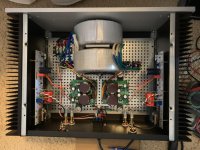
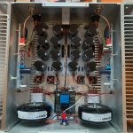
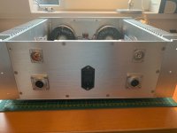
These last two builds look great. Steefdebruijn, what is that circuit board in the middle front for? To all, do these dual transformer and rectifier builds have noticeable advantages over a shared transformer and rectifier? I've always liked the stereo separation of mono amps. Do these do as well as mono amps?
what is that circuit board in the middle front for?
It is a soft start board with overheating protection. It is controlled by the momentary switch on the front. If one of the two temp sensors next to the amp boards on the heat sinks exceeds 75 degrees Celsius the amp switches off. Seems overkill so far because heatsinks are still indefinitely touchable after hours of playing music.
Only issue so far is that the amp does NOT switch off controlling the momentary push button if the amp has been singing for several hours. :-( I have no idea where to start investigating this. For now I switch off using the toggle on the IEC inlet when this happens
Steef
Have a look at post #55 written by Nelson Pass. You might decide to perform the experiment of replacing the 10uF capacitor with a short circuit, a piece of wire (!). Now you can perform a 3 way listening test. (i) cheap junkbox 10uF cap; (ii) super high quality 10uF audiphile cap; (iii) a piece of wire. Maybe you will hear huge differences. Maybe you will hear small differences. Maybe you will hear no differences at all. Try it and find out.does anyone know how important the quality of the 10uf capacitor? does it make a difference in the sound? Happy New Year!
If you want to fool around, you can eliminate the cap coupling.
The 10uF cap is in the signal path and different caps will have an effect on how the amp sounds. Tea-Bags board accommodate different cap types and sizes. This includes electrolytic with a film bypass cap, or large 10uF film caps. It is up to the builder to make the decision on what type of cap they want to use. The good thing the BOMs provided by Tea-Bag and the one for the M2x provide good options.
For my build I used Audyn Cap Q4 10uF 400V MKP Metalized Polypropylene caps. I like film caps, but did not want to spend a lot, so decided to give them a try. The amp sounds great, but do not know if they are any better than the BOM electrolytics. All I can say is that I’m very happy with M2 and don’t feel the need to make any changes.
Not sure if that helps, but those are my observations.
Is it possible that the 240 and 9240 biased at 1.3A+ and ranning without heat?
I have mine measured +0.65V and -0.65V across the two 0.47R, but both of the irfp240 and irfp9240 ran without heat. Not even warm.
But the amplifier sounds distorted and so little. Will it possible for both of the mosfet burned?
I have mine measured +0.65V and -0.65V across the two 0.47R, but both of the irfp240 and irfp9240 ran without heat. Not even warm.
But the amplifier sounds distorted and so little. Will it possible for both of the mosfet burned?
Is it possible that the 240 and 9240 biased at 1.3A+ and ranning without heat?
I have mine measured +0.65V and -0.65V across the two 0.47R, but both of the irfp240 and irfp9240 ran without heat. Not even warm.
But the amplifier sounds distorted and so little. Will it possible for both of the mosfet burned?
Post a copy of the schematic and the voltages that you measured at the most important points.
Hi, Thank you for your feedback, I have swapped 2 pairs of new irfp9240 and 240, swapped new optocoupler, swapped 385-1.2. But still the same, the mosfet does not get hot at all, I can even left it there without heatsink. the sounds is very soft and distorted badly.
The measurements look fine, I can adjust the offset from the trimmer too...
The measurements look fine, I can adjust the offset from the trimmer too...
Attachments
mind to post some pictures ?
that's really puzzling ......
evidently possible two culprits , not just one ........ one problem being problematic Iq (even if i'm more than confused - readings being OK , while there is no heat) ...... and another problem bad sound ..... can be connected , and doesn't need to be
from where you obtained input JFets?
- Home
- Amplifiers
- Pass Labs
- Official M2 schematic