henryve,
Sorry to hear about your troubles with the Edcor. Hope you can get it fixed without having to incur high shipping costs.
Thanks for the concern my friend. 😉
Well, just finished delicate operation. I think it was successful.
That is good news! 🙂
Hope you get both channels up and running soon!
Soldered the transformer back onto the PCB and did my continuity check again. All seems fine now. I checked from the junction between R3 and R4 to GND and to R5. Both PCBs measures the same now.
I always do some sanity checks before powering up the PCBs. Still waiting for my 330mOhm resistors then this project can come to completion.
I always do some sanity checks before powering up the PCBs. Still waiting for my 330mOhm resistors then this project can come to completion.
henryve,
Good to hear that no unpleasant surprises, and things are on track. Have you done the chassis work?
And if I may ask, you are using diyAudio store PCBs or Tea-Bag's ones?
Good to hear that no unpleasant surprises, and things are on track. Have you done the chassis work?
And if I may ask, you are using diyAudio store PCBs or Tea-Bag's ones?
I bought a Dissipante 4U/400 through the DIYAudio Store. I can do aluminium work with my woodworking machines, but I am too lazy.
Using the Tea-Bag boards.
Using the Tea-Bag boards.
Good choice of chassis henryve, and Tea-Bag boards are very good quality.
Doing chassis work is quite time consuming, so I would also go for a ready-made chassis. 😀
Doing chassis work is quite time consuming, so I would also go for a ready-made chassis. 😀
Did don-audio finish promotional sale edcore trafo by the voucher code DIYAUDIOCOM?
Last edited:
Many tries to squeeze the most juice out of amps. I wonder how to decrease gain of the M2. Can I increase source resistor, feedback or something else? Is it effortless to try? What will happen to the character?

Resistor divider with output of R2/(R1+R2). Am I on the right track? What would be a reasonable high input impedance? Mark, thank You for the hint!
Last edited:
Many tries to squeeze the most juice out of amps. I wonder how to decrease gain of the M2. Can I increase source resistor, feedback or something else? Is it effortless to try? What will happen to the character?
use classic repeater coil , connected to your will , giving you gain of 2V/V , or 4V/V , instead of 600:15K Edcor , which is giving you 6V/V
classic repeater is 600:600 xformer , nominally , and majority of them are having CT both on primary and secondary , effectively being 150+150:150+150
Edcor is having that in same form factor as 600:15K, which as direct drop in will give 4V/V
attenuating signal on input is good as temporary patch , but choosing that as permanent solution is ..... waste of signal energy
Many tries to squeeze the most juice out of amps. I wonder how to decrease gain of the M2. Can I increase source resistor, feedback or something else? Is it effortless to try? What will happen to the character?
How much do you want to decrease the gain?
To me the obvious answer is to use a 600:10k 0r 600:2400 transformer / autoformer in place of the 600:15K.
There is generally no penalty for lower step up if you do not need the gain.

Sometimes DC can not be set at standard resistors. As far as I understood correctly, this is due to catalog differences between N and P mosfet. Is the reason for Vgs? If so, is it possible to choose mosfets by measuring and Vgs instead of replacement the resistors R6 i R7 after assembly?
( Sorry for my english. I used google translate).
( Sorry for my english. I used google translate).
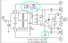
Both "6L6" and I have built M2 amplifiers using the modified, not-Nelson-Pass, parts values shown in the attached schematic in dark blue. Both of us are happy with the results, and both of us were able to achieve extremely low offset voltage at the output (sub 5 millivolts) in a couple hours of twiddling.
The main idea is that some M2 amplifiers need the upper green circle to have bigger resistance than the lower green circle. Other M2 amplifiers need the upper green circle to have smaller resistance than the lower green circle. Why? So that builders can cancel out the normal and unavoidable manufacturing variation in MOSFET threshold voltage (Q1 & Q2), MOSFET forward transconductance (Q1 & Q2), resistor tolerance (R13 & R14), and probably a few additional factors.
When P1 is dialled up to its maximum resistance, (R6+P1) = (37K + 20K) = 57K and this is comfortably greater than 47K (the value of R7). Good! We have achieved the first half of our goal.
When P1 is dialled down to its minimum resistance, (R6+P1) = (37K + 0) = 37K and this is comfortably less than 47K (the value of R7). Good! We have achieved the second half of our goal.
I think it's useful to spend a little extra money and buy a multiturn trimmer with as many turns as possible. Mouser part number 652-3296W-1-203LF (USD 2.41 qty 1) is one example of a 25 turn trimmer. This allows you to make small, fine-grained, adjustments.
_
Attachments
I got question about the M2 and heat. Mine has big heatsinks and I use fans, so the heatsink is barely warm, no problem there. However, I can barely touch one of the output transistors and even the nearby board itself is very hot. Bias is the same on all outputs. Why is one hotter? Can I decrease bias to all outputs?
I can smell slight burning...or am I just paranoid?
I can smell slight burning...or am I just paranoid?
- Home
- Amplifiers
- Pass Labs
- Official M2 schematic