I had very good experience with Plum Brandy iof ethanol...
Just remembered, Quince Brandy was even better! 🙂
Just remembered, Quince Brandy was even better! 🙂
Djole buddy ! Long time, no see - hope you're well...
I knew I shouldn't mention alcohol in such a distinguished company, but what the heck ! 😀
I knew I shouldn't mention alcohol in such a distinguished company, but what the heck ! 😀
Anybody have a couple of pair of 170/74 Jfets "A grade" they can spare. I have some lu1014 (6) from an abandoned F3 build (built F5), That I would trade as part of the deal. The lu1014 are as received, I don't know if they match or how they measure. I've read that the DiyStore may be offering matched pairs of Jfets in the future, but my build is done otherwise, and am wanting to finish it so I can get on with building the Cubie 2. Thanks.
OKEY DOKIE, In fear of exposing further ignorance, I installed the jfets I had and powered it up with +-15v. One side has (near as I can rekon') 9idss jfets and the other 13idss jfets. I initially changed the trim pots to 1K trimmers. (Not leaving it on for more than a second or two), I initially had ~3 amps on the positive power connection. I can dial one channel down to 2-2.5 amps, the other to 1.5 amps.
I tested the jfets with the actual power supply (15v) and read across a 10 ohm resistor. That got me 130mV and 90mv on each jfet in the respective pairs.
Do I bail on these jfets, or do I change the resistor that is in series with the trimmers. Do I change the trimmer to the original 500 ohm when I do this. Please answer as if I'm a graphic designer playing an EE on a soap opera. Thanks so much. The amp looks awesome, and as soon as I get it running, I'll post some pics!- marsupialx
I guess I should have tried shorting the fixed resistor and see how it measured. It would appear that with the pot at zero, the resistance is still too much. It sounds like degenerating the jfets this far will have deleterious effects on other balances (feedback) in the circuit. Perhaps the best bet is to use these in the Cubie 2 and wait to complete Cubie when I can find appropriate jfets. Thoughts, (or any beneficent jfet owners that can spare some ~3idss jfets) - Thanks (please forgive if I am babbling non-sense)
Marsu,
Cubie was designed for GR grade JFETs (Idss of 3-4mA or so) so obviously, when you installed BL grade JFETs you got too high Vgs and consequently too high Id in the output stage.
The remedy is simple:
Put back the original trimmers (500 R or even 200 R) and change R16/R17 (originally 390R) to 47 R or 100-150 R if you decide to use 200 R trimmers (for easier bias setting).
Change you Vds to 10Vds as specified in the datasheet......................
I tested the jfets with the actual power supply (15v) and read across a 10 ohm resistor. That got me 130mV and 90mv on each jfet in the respective pairs...............
Your 13mA Idss @ 15Vds is dissipating ~195mW. That is far too hot. The specification for Idss is Tj=25°C
If you only have a 15Vdc supply, then you can change your resistor to 390r. That will drop ~5V getting Vds down to 15-5= ~10V
The resistor dissipation will be 64mW, it will run cold to slightly warm.
Now your jFET is dissipating 130mW, still hot, but much better than 195mW.
You will probably discover than it is not a 13mA Idss device !
You can use a 100r for measuring current and add on an adjustable VR in series so that you can adjust the Vds to become 10Vds to match the datasheet specification.
BTW, low Idss stay cool to warm and the Tj error stays reasonably small. Medium Idss become less accurate, high Idss devices cannot be measured accurately using our constant DC methods.
That is one of the reasons I never recommend trying to do absolute measurements.
I recommend using "compare REF to DUT"
Last edited:
Marsu,
Cubie was designed for GR grade JFETs (Idss of 3-4mA or so) so obviously, when you installed BL grade JFETs you got too high Vgs and consequently too high Id in the output stage.
The remedy is simple:
Put back the original trimmers (500 R or even 200 R) and change R16/R17 (originally 390R) to 47 R or 100-150 R if you decide to use 200 R trimmers (for easier bias setting).
It seems like shorting the resistor and just letting the trimmer get to the necessary drop in bias resistance would work to let me find out the actual total resistance needed, before unsoldering stuff. Sounds like it should work. Thanks for your help!
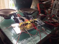
Cubie is biased at .7 amps per channel with 0 offset. It fluctuates a little. I will let it warm up tomorrow and tweak the bias. I had myself fabulously confused with top and bottom, copper side and part side. It dawned on me right before I posted the previous post. Thanks, juma!!! Thanks, Andrew!!! Will hook it up to some junk speakers tomorrow morning. Yeeeeeeeehaaaaaaaaaaw!😀
I ended up replacing the 390 ohm with 90 ohm and used the trimmer to get to the 119 ohm to 225 ohm range it required. Freakin' Awesome!!!!!
I ended up replacing the 390 ohm with 90 ohm and used the trimmer to get to the 119 ohm to 225 ohm range it required. Freakin' Awesome!!!!!
Last edited:
Change you Vds to 10Vds as specified in the datasheet.
Your 13mA Idss @ 15Vds is dissipating ~195mW. That is far too hot. The specification for Idss is Tj=25°C
If you only have a 15Vdc supply, then you can change your resistor to 390r. That will drop ~5V getting Vds down to 15-5= ~10V
The resistor dissipation will be 64mW, it will run cold to slightly warm.
Now your jFET is dissipating 130mW, still hot, but much better than 195mW.
You will probably discover than it is not a 13mA Idss device !
You can use a 100r for measuring current and add on an adjustable VR in series so that you can adjust the Vds to become 10Vds to match the datasheet specification.
BTW, low Idss stay cool to warm and the Tj error stays reasonably small. Medium Idss become less accurate, high Idss devices cannot be measured accurately using our constant DC methods.
That is one of the reasons I never recommend trying to do absolute measurements.
I recommend using "compare REF to DUT"
Thanks to induce my reasoning. Good weekend.

Marsu, you don't need that terrible twisting of output MOSFETs' pins. They should be soldered from the bottom side of PCB. Just look carefully at the pics in post #1.
It's not "terrible twisting", it's a neat semi-circle bent around a cylindrical former. The board will hang from a heatsink above it. It's an easier (less terrible) bend than doing a right angle (which is common). The board is small and relatively light, and can move slightly with expansion and contraction. It is out of its own way for mounting screws. But that's cool. It at least was not done without forethought, right or wrong. My amp may be quite non-conformist, but that is the fun. We shall see... I'm the only one that's got money(time) riding on it... I certainly don't encourage others to build amps like I do!!! Thanks for the cool amp circuit!!!
Thanks for the cool amp circuit!!![/QUOTE]
And for patience with us who have yet to have formed an adequate mental framework.
I am in awe at the members of this fabulous forum that are fluently conversant in electronics.
Even if Cubie 2 outperforms Cubie, having a discrete amplifier with so few parts is amazing. It is flat out cool.
Replacing the trimmers with lower values than the 1K I used initially made biasing and dc offset way easier (less twitchy and more precise.)
I can testify that soldering a part's lead into the wrong hole can cause less than ideal performance characteristics.😀
I'm not rushing the final assembly, even tho' I am tempted.
One step at a time, fail miserably, same step again, do it better, next step. Come up with a more elegant solution for what you did three or four steps ago, try it, fail miserably, do it better. And so it goes...
Sure, that's how it goes, it's just that your "neat semi-circle bent" doesn't look very good from point of long-term reliability but I'm sure you'll find about that without my help, so in future I'll refrain from comments that offend you. 😉...One step at a time...

No offense taken. i realized my post sounded like that, but I was simply explaining my thought process. Please don't withhold info to try to avoid mashing my marshmallow. I went through intense critiques regularly in college, and have learned a great deal from them.
I need to revisit (at some point), my F5 build for the same concern, opposite cause. The mosfets are clamped into place with no freedom for expansion/contraction, and I think with time metal fatigue will take its toll.
It's always somethin'.😀
I need to revisit (at some point), my F5 build for the same concern, opposite cause. The mosfets are clamped into place with no freedom for expansion/contraction, and I think with time metal fatigue will take its toll.
It's always somethin'.😀
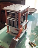
Cubie. Built to be small and unconventional. Very fun. Ten aluminum chimneys, four copper chimneys also acting as structural pillars. More detailed photos to follow. Little persnickety details left to do. Haven't listened to it yet except on unmounted junk drivers. Three layers, transformer, power supply, and amplifier. Design, saw, file, drill, fit, sand, repeat... Thanks, juma!
Attachments
- Home
- Amplifiers
- Pass Labs
- Cubie - small F5 variant with GR grade JFETs and LatFETs