Great work dBel84! Kudos!
I did as myleftear told and piggypacked a 10Kohm resistor and now I fixed the bias to 200mV!
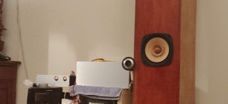
I have 96db fostex speakers and I plugged it on a 2V source DAC.
Some findings:
1) In terms of volume I really don't need an amplifier, it is not party volume but is enough for the neighbours to complain! That was great finding
2) In terms of sound is the simply the best amplifier I have built, no other comments here, it is incredible.
Some questions as always now!:
1) I measure the bias resistors and not all transistors are at 200mV, some are at 180mV and some at 205mV, is this right?
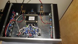
2) I have a mechanical buzz on the transformer which is audible from the 96dB speakers. You have to move your ear near the speaker to hear it, so it is not critical. The transformer has an interwind shield, I have connected on the earth ground after the thermistor and not on the power supply ground. Do you think that if i connect it to the power supply ground can help here? Do you think than I should change the transformer?
Is these current pulses as Zen Mod said before and I need to check the wiring of the capacitors?
Thanks everybody for all the help again!
I did as myleftear told and piggypacked a 10Kohm resistor and now I fixed the bias to 200mV!
I have 96db fostex speakers and I plugged it on a 2V source DAC.
Some findings:
1) In terms of volume I really don't need an amplifier, it is not party volume but is enough for the neighbours to complain! That was great finding
2) In terms of sound is the simply the best amplifier I have built, no other comments here, it is incredible.
Some questions as always now!:
1) I measure the bias resistors and not all transistors are at 200mV, some are at 180mV and some at 205mV, is this right?
2) I have a mechanical buzz on the transformer which is audible from the 96dB speakers. You have to move your ear near the speaker to hear it, so it is not critical. The transformer has an interwind shield, I have connected on the earth ground after the thermistor and not on the power supply ground. Do you think that if i connect it to the power supply ground can help here? Do you think than I should change the transformer?
Is these current pulses as Zen Mod said before and I need to check the wiring of the capacitors?
Thanks everybody for all the help again!
Attachments

Great work dBel84! Kudos!
I did as myleftear told and piggypacked a 10Kohm resistor and now I fixed the bias to 200mV!
I have 96db fostex speakers and I plugged it on a 2V source DAC.
Some findings:
1) In terms of volume I really don't need an amplifier, it is not party volume but is enough for the neighbours to complain! That was great finding
2) In terms of sound is the simply the best amplifier I have built, no other comments here, it is incredible.
Some questions as always now!:
1) I measure the bias resistors and not all transistors are at 200mV, some are at 180mV and some at 205mV, is this right?
2) I have a mechanical buzz on the transformer which is audible from the 96dB speakers. You have to move your ear near the speaker to hear it, so it is not critical. The transformer has an interwind shield, I have connected on the earth ground after the thermistor and not on the power supply ground. Do you think that if i connect it to the power supply ground can help here? Do you think than I should change the transformer?
Is these current pulses as Zen Mod said before and I need to check the wiring of the capacitors?
Thanks everybody for all the help again!
xformer static shield (blind winding, whatever) goes to case metal, so safety gnd
no use of polluting audio gnd with it
one of these days I'll find adequate sketch to explain how to properly wire those cap banks
It would be great Zen Mod, I think it will help other members that may want to wire the caps point to point!
I studied the presentation you posted before and I think I made some improvements but maybe I still need some help!
I studied the presentation you posted before and I think I made some improvements but maybe I still need some help!
Nice build!!!
I have a Fostex 167E at 94dB as backup speakers. Yes, sounds good with the Fostex. I am using Type 26 and 01A preamp.
I used 400VA in my F4 so no shield, but in my M2X, I have the transformer shield connected to chassis ground at first, then later move it to the GND of the H9KPXG (to eliminate a long wire). Both arrangement are quiet.
As for the bias resistor voltage reading, the small difference could be from the tolerance of the resistors (0.38 amps for 180 mV and 0.436 amps for 205 mV) or temp gradient near the resistors when the MOSFET's are just heating up. Have you tried increasing the bias to 250 mV and then wait for 30 minutes then measure the voltage?
I have 96db fostex speakers and I plugged it on a 2V source DAC.
I have a Fostex 167E at 94dB as backup speakers. Yes, sounds good with the Fostex. I am using Type 26 and 01A preamp.
I have to agree. I have the M2X and it sounds great, no question! But the F4 is so transparent with what's driving it and I have very good experienced with 45, 2A3 and 300B SET tube amps and SE El34 amps in front of the F4.Some findings:
2) In terms of sound is the simply the best amplifier I have built, no other comments here, it is incredible.
Some questions as always now!:
1) I measure the bias resistors and not all transistors are at 200mV, some are at 180mV and some at 205mV, is this right?
2) I have a mechanical buzz on the transformer which is audible from the 96dB speakers. You have to move your ear near the speaker to hear it, so it is not critical. The transformer has an interwind shield, I have connected on the earth ground after the thermistor and not on the power supply ground. Do you think that if i connect it to the power supply ground can help here? Do you think than I should change the transformer?
I used 400VA in my F4 so no shield, but in my M2X, I have the transformer shield connected to chassis ground at first, then later move it to the GND of the H9KPXG (to eliminate a long wire). Both arrangement are quiet.
As for the bias resistor voltage reading, the small difference could be from the tolerance of the resistors (0.38 amps for 180 mV and 0.436 amps for 205 mV) or temp gradient near the resistors when the MOSFET's are just heating up. Have you tried increasing the bias to 250 mV and then wait for 30 minutes then measure the voltage?
Last edited:
Hello,
the resistors I have used are 1% tolerance (https://gr.mouser.com/ProductDetail/71-PAC300004707FAC00/)
I changed the bias to 250mV after an hour and waited for 30 minutes, the transistors are now between 230mV and 250mV. The transistors have been bought from diyaudio store so the source is trusted!
the resistors I have used are 1% tolerance (https://gr.mouser.com/ProductDetail/71-PAC300004707FAC00/)
I changed the bias to 250mV after an hour and waited for 30 minutes, the transistors are now between 230mV and 250mV. The transistors have been bought from diyaudio store so the source is trusted!
I have noticed a very odd behavior in one channel with my F4. While playing music, it intermittently "gets soft" in the left channel - almost like I had a fader and the the music was redirected to one channel more than the other and then it comes back as normal.
1. it is not the music, source or preamp as I switched out the L/R signals into the amp and the odd behavior stays with the same channel
2. while I was burning it in / setting it up the bias was solid - climb slowly as the amp heated up but no variance , same for the offset. Initial flux at power up but settles quickly to .1mV and doesn't move about
I can't believe it would be the output devices as trouble with them would more likely result in major amp failure so looking at the input section.
I am using original ( matched ) Toshibas ( no doubt that they are real ie not fakes)
any ideas as to what to measure to identify what might be going on.
thanks..dB
Hi nikos, now you have a full functional amplifier.
I will wait for your listening impressions.
Thimios
I will wait for your listening impressions.
Thimios
I have noticed a very odd behavior in one channel with my F4. While playing music, it intermittently "gets soft" in the left channel - almost like I had a fader and the the music was redirected to one channel more than the other and then it comes back as normal.
1. it is not the music, source or preamp as I switched out the L/R signals into the amp and the odd behavior stays with the same channel
2. while I was burning it in / setting it up the bias was solid - climb slowly as the amp heated up but no variance , same for the offset. Initial flux at power up but settles quickly to .1mV and doesn't move about
I can't believe it would be the output devices as trouble with them would more likely result in major amp failure so looking at the input section.
I am using original ( matched ) Toshibas ( no doubt that they are real ie not fakes)
any ideas as to what to measure to identify what might be going on.
thanks..dB
if intermittent problem, doubt fishy soldering somewhere
if intermittent problem, doubt fishy soldering somewhere
agreed - I decided to reflow all the solder joints just in case

I put it back on the bench and both sides seem to have similar measurements wherever I probed. I cranked up the bias from 250 to 300 mV ( 530mA to 630mA per device ) , heatsinks were only sitting at 40 degC after 2 hours so I thought I had plenty of headroom and based on 6L6 measurements ~ 600mA seems to be the sweet spot .
Going to leave it to settle for another few hours and then test it on speakers again. It appears to be behaving like it is anticipated
Another happy F4
F4 build is complete. It's been going for 2-3 hours, I've worked through the bias and 0 DC adjustments, and it's sounding good.
I do have an issue with bias on one channel. The voltages across the 3W resistors are currently:
Is this telling me that the MOSFET at R17 is poorly matched with the others?
F4 build is complete. It's been going for 2-3 hours, I've worked through the bias and 0 DC adjustments, and it's sounding good.
I do have an issue with bias on one channel. The voltages across the 3W resistors are currently:
- R16: 0.215v
- R17: 0.185v
- R18: 0.215v
- R19: 0.205v
- R20: 0.205v
- R21: 0.205v
Is this telling me that the MOSFET at R17 is poorly matched with the others?
it's in 15%, don't fret
just the reason that next time (next amp needing matched parts) - invest some elbow grease in own matching
just the reason that next time (next amp needing matched parts) - invest some elbow grease in own matching
and I found my auidophool problem
I decided I would get some better "audiophile" parts for this build and bought some KLEI RCA connectors - turns out my RCA doesn't fit snugly and with even the slightest of movement - the ground connection gets lost.
Lesson learned - stick with neutrik which I know works well and has never failed me.
..dB
I had this same issue on my BA 2018 linestage that threw me off for awhile. I'm not a big fan of RCA connectors in general.
Thanks. I've been noodling on this and decided it is what it is, and I'm glad to get the reassurance. This is my first build, so I'm not going to kick myself if this is the biggest mistake I made.it's in 15%, don't fret
just the reason that next time (next amp needing matched parts) - invest some elbow grease in own matching
But I just can't let it pass
I'm just curious ;-)
If I replaced R11 (the resistor in front of the gate) with a pot, I could bring that MOSFET in line. Yes?
it's in 15%, don't fret
just the reason that next time (next amp needing matched parts) - invest some elbow grease in own matching
I'm just curious ;-)
If I replaced R11 (the resistor in front of the gate) with a pot, I could bring that MOSFET in line. Yes?
No. You probably have a 0.47 3W that’s off a little. Those are hard to measure without a good meter.
Again, as Zen said, don’t worry about it.
Again, as Zen said, don’t worry about it.
No. You probably have a 0.47 3W that’s off a little. Those are hard to measure without a good meter.
Again, as Zen said, don’t worry about it.
I guess what I was suggesting is putting a cheese grater in the signal path. My "other amp" has six power tubes, each of which has a pot for bias. But, looking at it now, the tube bias is changing the cathode voltage, while the grid is what influences signal. With transistors, the gate is both signal and bias. Am I getting this right?
whichever way you change grid-cathode voltage (bias), is changing tube Iq
whichever way you're changing gate-source voltage (bias), is changing mosfet (JFet) Iq
whichever way you're changing gate-source voltage (bias), is changing mosfet (JFet) Iq
Has been making wonderful music for the past few days, all stable and sounds absolutely fantastic.


Thank you all for the ongoing support and opportunity to build this amp. It may actually be my favourite thus far. ( and it goes without saying , much appreciation to Nelson for making all this fun possible )
..dB
Thank you all for the ongoing support and opportunity to build this amp. It may actually be my favourite thus far. ( and it goes without saying , much appreciation to Nelson for making all this fun possible )
..dB
- Home
- Amplifiers
- Pass Labs
- A guide to building the Pass F4 amplifier