1. 86/82 are magic numbers: I found two articles at Conrad - No. 189056 and 189058
2. no need for thermal goo and it'll be counterproductive
3. too thin for out, unless you use more wires
4. wiring of caps is not good; see enclosed pic and think of pulse current distribution
5. do not power on until you get proper insulators!!!; use mica and grease (if you have them or if it is faster to get them), in case of F4 they're not critical at all; do not forget split washers at mosfet bolts!!!
disclaimer - Keratherms you have are maybe even good enough for F4 (not too much heat per one mosfet) but as matter of priciple .......... I had wrongly delivered exactly that type of K. instead of proper one, and I didn't even checked what's written on bag sticker ....... and it costed me dearly....... blown pair of Dynaudio drivers, time, scorched pcbs....
Attachments
Last edited:
I bought this keratherm from Conrad. I think it is exact the same like in diyaudiostore.com Folia termoprzewodząca Kerafol 86/82 czerw. 100X100X0,25 mm | Zamow w Conrad.pl
A
Also, I built a Bulb Tester to be ready for when I will power the amplifier for the first time! I haven't thought of that before! What a clever tool! I highly suggest it for novice builders like me!
For a proper test-sequence with the lightbuld, the masters recommend to check one part before the next—1st PSU, if good connect 1 amp, if good connect other.
If you’re sure about your build, do as you think is good enough.
(I am very cautious, for reasons)
(i found those: Kerafol 86/82 Thermally conductive film 0.25 mm 6.5 W/mK (L x W) 100 mm x 100 mm | Conrad.com , same as in the store but not to220 or something—you could cut them yourself and still have way better heat transfer?)
Last edited by a moderator:
I am waiting for wires with different color so I will hook the board with them as 6L6 suggested and also I will insulate the CL-60.
Right now I have tested only the PSU and I will proceed as myleftear suggests.
So for the Keratherm and the effort to avoid disasters like the one mentioned my Zen Mod, I have also this:
SCI A18-9E Semiconductor mounting set (L x W) 22.3 mm x 15.2 mm Suitable for TO 247 1 Set | Conrad.com
Is this better or should I order the 86/82 type?
These questions may seem naive but the terminology in electronics is different in Greek language and sometimes makes it difficult to find the right part, even if it is something simple!
Zen Mod In the photos I use the kit from the diyaudio store, you believe I should change these washers with split type?
For the wiring of caps you mean that the paths for the negative and positive power supply are of different length or you mean that all the wiring on the caps is wrong? If I am completely out of subject here please ignore it and I will check further on this!
can't be sure thingie is Alu-oxide type, or something like that, which is good one (thermal goo necessary)
all what I can read in data is - ceramic-
without more details or at least C/W figure, no go
washers - you need both big ones and split ones
split ones are safety parts here - thermal cycling is tricky thing
will try tomorrow to edit one of your pics, if you don't catch that cap wiring by your self in meantime
Great Presentation Zen Mod! I will study it thoroughly after work today!
Thank you very much!
Highly appreciated!
Thank you very much!
Highly appreciated!
yes, if you adjust value of source resistors, to set them somewhere at 7-8mA
think dissipation, nothing else
think dissipation, nothing else
So for the Keratherm and the effort to avoid disasters like the one mentioned my Zen Mod, I have also this:
SCI A18-9E Semiconductor mounting set (L x W) 22.3 mm x 15.2 mm Suitable for TO 247 1 Set | Conrad.com
Is this better or should I order the 86/82 type?
These questions may seem naive but the terminology in electronics is different in Greek language and sometimes makes it difficult to find the right part, even if it is something simple!
These look suspiciously close to the ones I am using on the ClassA's including the F4 balanced monos - due to their excellent heat transfer, however I am using these with heat paste! It is ceramic discs, they are flat - and they are brittle, so if the heat sink isn't perfectly flat they might either break or not get a good thermal contact with a nice thin layer of paste. That said I am very pleased with the performance. 😎
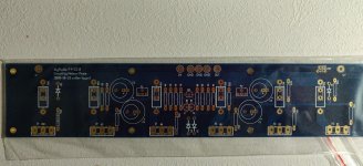
F4 unpopulated board pic?
Hi friends
I'm tele-investigating my F4 build-history due to something not working (debug-assistance is underway in my separate thread)...
I find it a bit difficult to lookup parts-positions on the populated board, and I couldn't find a drawing or foto in a high enough resolution to look up positions.
So, has someone a board that isn't populated, who would like to make a picture of it in a high-enough resolution that the smallish part-denominators are readable?
I'd gladly make a infinitely zoomable pdf-drawing of it for all interested fellows...
thank you!
david

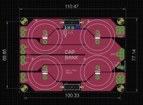
Virtual F4 (drawing of the board, kind of a stuffing-plan)
Thanks to all for their support!
As little as I can return, here it is—I just took the various sources of the boards cvilletypor made and made a graphic out of it.
Thus, IF anyone once might be in need to identify a part on the board hidden in the chassis, this may help a little.
I flatly copied the labels (and verified that Q10 IS Q10 for whatever reason), so that everything fitted the foot of the board...
There are 2 Versions: a colored one, better for onscreen view (and you can search for text 😉 ), and 2 outline b/w versions (with type vectorized, not searchable).
For easier view, I put all labels horizontally. This may be problematic for printing because the text is rather small...
HTH
d.
Attachments
Last edited:
Thank you for sharing that!
Perhaps Jim can include a link in the first post so others can easily find this.
Perhaps Jim can include a link in the first post so others can easily find this.
- Home
- Amplifiers
- Pass Labs
- A guide to building the Pass F4 amplifier