Hello all, great topic and very informative!
I have started my F4 build yesterday.
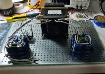
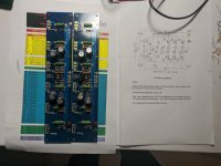
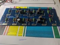
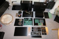
I finished the power supply and I have populated the channels boards with everything except the MOSFETS and the potentiometers!
The kit from the diyaudio shop along the case from modushop makes a great diy friendly build! Having the comments of these forum is of invaluable help also!
Some minor questions if someone could help here:
1) For the power transformer I have used the Signal 400VA (https://gr.mouser.com/ProductDetail/530-MPI-400-36/) Is it any good or I should look for something else?
2) I have used 25Volt capacitors for the power supply (https://gr.mouser.com/ProductDetail/75-80D153P025KE2DE3/), are they good and more important will it blow? 🙂
3) Finally I used these capacitors for the channels (Access to this page has been denied.) do you think I should replace them with something from Panasonic?
I will try to post finished build photos when I receive all the components!
I have started my F4 build yesterday.
I finished the power supply and I have populated the channels boards with everything except the MOSFETS and the potentiometers!
The kit from the diyaudio shop along the case from modushop makes a great diy friendly build! Having the comments of these forum is of invaluable help also!
Some minor questions if someone could help here:
1) For the power transformer I have used the Signal 400VA (https://gr.mouser.com/ProductDetail/530-MPI-400-36/) Is it any good or I should look for something else?
2) I have used 25Volt capacitors for the power supply (https://gr.mouser.com/ProductDetail/75-80D153P025KE2DE3/), are they good and more important will it blow? 🙂
3) Finally I used these capacitors for the channels (Access to this page has been denied.) do you think I should replace them with something from Panasonic?
I will try to post finished build photos when I receive all the components!
Attachments
1) Power transformer seems fine. You'll know when you put a load on it...If it hums you'll be looking for something else.
2) In the future order something with a little safety margin...35V or even 50V.
3) Just go with what you've got.
Looking forward to seeing pics of a working amp!
2) In the future order something with a little safety margin...35V or even 50V.
3) Just go with what you've got.
Looking forward to seeing pics of a working amp!
Thank you guys,
So i will continue like this and I will check on the final sound!
Or did Zen Mod by "check" meant I should change them all?! 🙂
So i will continue like this and I will check on the final sound!
Or did Zen Mod by "check" meant I should change them all?! 🙂
With a long line of projects lining up  finally got to finish a set of F4's
Simply couldn't get sufficient heat into the F5's running them as monos. This wasn't entirely unexpected as the ceramic heat transfer pads do work well.
Rebuilding to F4 dual balanced mono's solved that issue. Temperature is stable just above 50C, so all good.
So many here seem to be running the ClassA's cold in huge cabinet's....
I don't mind a little heat - In fact I grew up making Class A's, JLH's Hiraga etc.
If you didn't burn your fingers on the heatsinks, it meant something had gone wrong in the build: cold amp = defect amp 😛
However talking about big cabinet's it quite quickly get painful when too compact, keep promising myself that next time I will leave ample space for working on the things. Next I will probably not be able to resist cramming in an extra set of electrolytics, to again prevent a clear look at the baseplate 🙂
Some notes:
Biased as std. @ 0.43A,
rails at just below 23V, RC: 3x//.56R & 4x6x56mF/35V
Stable, easy to adjust - only slow Matched sextets in each unit (not needed but because I had them) A bit dull compared to a recent Doxa adjustment, which was like catching butterflies with your bare hands...
No hum, no noise, nice ambience, nice clarity - nice amp
Thanks Nelson! & Thanks to everybody else especially 6L6 and ZM for an inspiring thread!
Now on to the V4H's, a pre-amp that can drive the things properly and those X-overs.....
finally got to finish a set of F4's Simply couldn't get sufficient heat into the F5's running them as monos. This wasn't entirely unexpected as the ceramic heat transfer pads do work well.
Rebuilding to F4 dual balanced mono's solved that issue. Temperature is stable just above 50C, so all good.
So many here seem to be running the ClassA's cold in huge cabinet's....
I don't mind a little heat - In fact I grew up making Class A's, JLH's Hiraga etc.
If you didn't burn your fingers on the heatsinks, it meant something had gone wrong in the build: cold amp = defect amp 😛
However talking about big cabinet's it quite quickly get painful when too compact, keep promising myself that next time I will leave ample space for working on the things. Next I will probably not be able to resist
cramming in an extra set of electrolytics, to again prevent a clear look at the baseplate 🙂Some notes:
Biased as std. @ 0.43A,
rails at just below 23V, RC: 3x//.56R & 4x6x56mF/35V
Stable, easy to adjust - only slow Matched sextets in each unit (not needed but because I had them) A bit dull compared to a recent Doxa adjustment, which was like catching butterflies with your bare hands...
No hum, no noise, nice ambience, nice clarity - nice amp
Thanks Nelson! & Thanks to everybody else especially 6L6 and ZM for an inspiring thread!
Now
on to the V4H's, a pre-amp that can drive the things properly and those X-overs..... Attachments
Last edited:
It indeed is - and they are good, prefer them to Talema a.o.
My 1Kva Talema's and 5-600va Ulveco's sound like angry grizzly bears if there is any trace of DC on the mains. -> Have to run DC filters on everything here.
Tight fit though (in 3U Mini's), the baseplate is lowered and heatsinks fitted higher on the brackets to make it possible, but I much prefer to minimize the stray field towards the boards by having the toroid upright, making the most of the flat field of the toroid.
Typically there is more leakage at the wire in/out-let - which I expect is part of the reason why these are always turned towards the front on the Firstwatt's
Later into the night yesterday the F4's got eye's in the front - to be seen and not stumbled upon in the dark 😎
Standard build, however the TL431 is an 40uA NCP type and the R9's had to be paralleled 10K//100k -> 9.1K to achieve the class A bias.
Coincidentially I had some ice-blue LED's that actually are close in color to the Pass build, only these were extremely & annoyingly bright, it took 1.5Mohm to get rid of the blinding effect.
Last edited:
Nice build Norgaard!
One not very relevant question, if anyone knows:
There are some thermal tapes like this one:Heat Sink Thermal Tape - 3M 8810 - 25mm x 25mm Australia
This kind is used with ICs for adding a heatsink on top. Is it any good for MOSFETS?
I have some spare and I was wondering if I can omit using mica and grease and use this tape instead.
Thermal conductivity is not very good—I wouldn‘t go lower than what keratherm gives (6.5W/mK)
Thanks! 🙂
You can use the tape - but it could quickly become a bit of a nightmare if you have less than perfect alignment, on clean surfaces they stick really well - so you've got one shot at the alignment
- Still due to the potential strain from the component legs & thermal expansion I would be worried about lift-off in the long term, if you do not torque down the transistors.
And yes the thermal conductivity of this type is actually quite a bit poorer than for typical gap-filler materials.
Last edited:
softstart...
yet another question out of my ignorance:
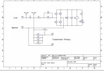
the security-cap between hot and neutral comes before any part (like, switch, softstart etc. … ?)
my guess = yes.
🙄
yet another question out of my ignorance:
the security-cap between hot and neutral comes before any part (like, switch, softstart etc. … ?)
my guess = yes.
🙄
…and the ground…
uhm.
sorry, me again, basic question #100'000'000:
The ground-star, which goes from PSU-ground to CL60 (or 35A diode or something), is "the only connection to chassis"?
There's no connection from the IEC to the chassis?
What do I do with the toroid's earth then?
many thanks
d.)
uhm.
sorry, me again, basic question #100'000'000:
The ground-star, which goes from PSU-ground to CL60 (or 35A diode or something), is "the only connection to chassis"?
There's no connection from the IEC to the chassis?
What do I do with the toroid's earth then?
many thanks
d.)
The X cap is for spark suppression on the mains switch and some noise filtering. It needs to be effectively across the switch.
IEC safety earth - of course you attach it to chassis!!! The “only connection to chassis” comment is about the audio circuitry.
IEC safety earth - of course you attach it to chassis!!! The “only connection to chassis” comment is about the audio circuitry.
why don't we solve that with exact PSU schematic you're using, so we can deal with particulars and explain all little details?
chassis must be connected with mid IEC pin, that's most basic and important thing
p14/16, http://www.firstwatt.com/pdf/prod_f4_man.pdf
chassis must be connected with mid IEC pin, that's most basic and important thing
p14/16, http://www.firstwatt.com/pdf/prod_f4_man.pdf
why don't we solve that with exact PSU schematic you're using, so we can deal with particulars and explain all little details?
chassis must be connected with mid IEC pin, that's most basic and important thing
p14/16, http://www.firstwatt.com/pdf/prod_f4_man.pdf
Thank you too, mighty zm! Just didn't see you were replying that fast, too!
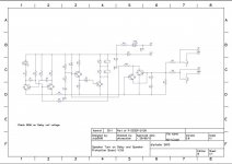
I work with diyaudiostore's stuff:
softstart-board
toroidy 2 x 18V 500VA "audiograde"
universal PSU, with discrete diodes, 8 bloody 47000UF 20% 35V caps, all classic...
F4 boards
speaker delay/DC-protection (powered by a 24V 2.3VA transformer, perfect!)
schematics attached, even though I did not work with it (I just barely can identify parts and connections, but don't understand schematics).
I'm veeery slooowly building my little beast, make about everything 2-3 times (until I'm satisfied/know it has to be this way),
and of course there's another 100'000'000 questions waiting, but they're all, uhm, not very important, but it is still thrilling to wait and see what little details you have for me... 😎
(Some of the not-so-little details are already set, and unless they prove to be totally bad decisions, they will stay that way (like, the toroids position etc.)
Pictures of my build unavailable until mañana.
Attachments
Last edited:
ok, you probably solved dilemma about safety gnd/chassis and audio gnd connection
if you think you need guardian angel(s) to complete you amp, best way is to open dedicated thread, use it as your own photo/graphical diary and place to get all tiny advices
everyone will contribute and enjoy that, when things are sort of organized
frankly, I'm sometimes lost with "hit & run" questions - did I replied or I didn't, am I in proper thread etc.
🙂
A happy new year with a lot of builds and listening!
Finally, some more parts arrived so I post some new photos!
And here are some question!🙂
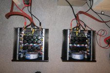
1) It is difficult in Greece to find the right parts sometimes. I found these Kerafol foils (Kerafol Thermally conductive film for semiconductor enclosures 0.25 mm 1.4 W/mK Suitable for TO 247 70/50 TO-247 | Conrad.com) They are not the same as in diyaudio shop. The conductivity is about 1.4W/mK. Someone else has asked this question again but he did not receive an answer so I believe that can help others located in Europe also. Is this part good or should I change it to mica?
2) Furthermore is it right that you just put it between the transistor and the heatsink and it works from the pressure of the bolt? I find it doesn't stick.
3) For the cabling of the input signal I used CAT-5 solid core wire. If I use it for the output is it too thin? I am asking because I have connected my speakers (Vulcan Woden Design) to my current amplifier (a modded TPA3116D2) with such a cable.
4) Do you see anything particularly wrong from the photos?🙂
I have never built an expensive amplifier (I have built only Class-D in the past) and I am a little anxious for the results!
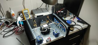
Also, I built a Bulb Tester to be ready for when I will power the amplifier for the first time! I haven't thought of that before! What a clever tool! I highly suggest it for novice builders like me!
Hope these questions can help other builders too! 🙂
Finally, some more parts arrived so I post some new photos!
And here are some question!🙂
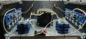
1) It is difficult in Greece to find the right parts sometimes. I found these Kerafol foils (Kerafol Thermally conductive film for semiconductor enclosures 0.25 mm 1.4 W/mK Suitable for TO 247 70/50 TO-247 | Conrad.com) They are not the same as in diyaudio shop. The conductivity is about 1.4W/mK. Someone else has asked this question again but he did not receive an answer so I believe that can help others located in Europe also. Is this part good or should I change it to mica?
2) Furthermore is it right that you just put it between the transistor and the heatsink and it works from the pressure of the bolt? I find it doesn't stick.
3) For the cabling of the input signal I used CAT-5 solid core wire. If I use it for the output is it too thin? I am asking because I have connected my speakers (Vulcan Woden Design) to my current amplifier (a modded TPA3116D2) with such a cable.
4) Do you see anything particularly wrong from the photos?🙂
I have never built an expensive amplifier (I have built only Class-D in the past) and I am a little anxious for the results!
Also, I built a Bulb Tester to be ready for when I will power the amplifier for the first time! I haven't thought of that before! What a clever tool! I highly suggest it for novice builders like me!
Hope these questions can help other builders too! 🙂
Attachments


That looks quite nice so far!
The insulators are good material for the job and mounted correctly.
Cat5 makes wonderful small signal wiring.
The exposed legs of the CL-60 on the transformer have the full mains on them, please insulate.
Please get wire with different color for wiring PSU to the amplifier boards. Keeping track of everything when all white will be a challenge, and nearly impossible to troubleshoot on the forum if needed.
Things appear good, carry on!
Last edited:
- Home
- Amplifiers
- Pass Labs
- A guide to building the Pass F4 amplifier