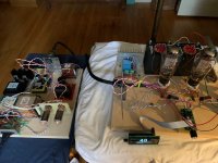
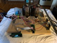
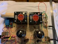
Just got some pictures of my new DHT pre......
ha!
no porn, no glory
ha!
no porn, no glory
Ask and ye shall receive good sir.
Attachments

Ask and ye shall receive good sir.
For the sake of accuracy, I should note that I failed to include the capacitor & 3 resistors going from cathode to ground as part of my signal path outline because I barely understand circuits and am an idiot. But today I learned. Been pouring over dht design discussions to figure out what I can.
Hi, finished building my F4 from buying the Amp board/Transistors/PSU board from the store and getting all other components from Digikey based on the BOM provided here.
After assembling and biasing the unit the sound seems fine in low volume but when I crank up the volume there is a significant distortion in the sound.
Biasing: From cold I set both channels to 0.13V and 0 DC offset (following the build guide) and after 30 to an hour I set the bias to 0.20V.
I used a single Triad magnetics toroid VPT36-6940
Blocked
I reviewed all solder joints but cannot see any issues at all. I also noticed that my ACA sounds better and louder that the finished F4.
Please, I am seeking help from the masters out there.
Thanks in advance.
Hi,
Not a master but getting same result with a different preamp? When you crank up the volume, what happens to the 200 mV bias?
Not a master but getting same result with a different preamp? When you crank up the volume, what happens to the 200 mV bias?
Last edited:
Hi, finished building my F4 from buying the Amp board/Transistors/PSU board from the store and getting all other components from Digikey based on the BOM provided here.
After assembling and biasing the unit the sound seems fine in low volume but when I crank up the volume there is a significant distortion in the sound.
Biasing: From cold I set both channels to 0.13V and 0 DC offset (following the build guide) and after 30 to an hour I set the bias to 0.20V.
I used a single Triad magnetics toroid VPT36-6940
Blocked
I reviewed all solder joints but cannot see any issues at all. I also noticed that my ACA sounds better and louder that the finished F4.
Please, I am seeking help from the masters out there.
Thanks in advance.
I'm no master, but do have two thoughts.
1. The aca will be louder. Note that it has 14db gain VS 0 in the f4.
2. I wonder if your transformer is under powered. Many use 400v or 500v transformers to run stereo builds. You're at 250v with that unit.
I was suspecting that the VA was a bit low for my tranfo, but how would I know if that is really the case without getting a higher VA transfo?
As cal3713 pointed out, the F4 does not have any gain, voltage gain, that is. In other words, it does not amplify voltage so the source that is feeding it needs to have fairly high voltage output capability.
So with the same source (music source, preamp, volume control) connected to the ACA and F4 and if the source is only capable of low voltage output, the ACA will sound louder.
keps, what are you using as sources?
So with the same source (music source, preamp, volume control) connected to the ACA and F4 and if the source is only capable of low voltage output, the ACA will sound louder.
keps, what are you using as sources?
No, you do not need to do anything with V+ or V-. Just disconnect the input to one channel, say L channel, and try if you can duplicate the result (distorted output sound at high volume). Please make sure it is not your preamp. Your laptop will have difficulty driving the F4 directly.
Last edited:
The transformer is not the problem.
Your preamp has neither enough gain nor voltage swing to run F4. The preamp is clipping, and F4 is happily and accurately reproducing it.
Your preamp has neither enough gain nor voltage swing to run F4. The preamp is clipping, and F4 is happily and accurately reproducing it.
Thanks to everyone, I will be getting a new preamp with a higher gain soon, I will share the outcome when I get a hand on it.
As cal3713 pointed out, the F4 does not have any gain, voltage gain, that is. In other words, it does not amplify voltage so the source that is feeding it needs to have fairly high voltage output capability.
So with the same source (music source, preamp, volume control) connected to the ACA and F4 and if the source is only capable of low voltage output, the ACA will sound louder.
keps, what are you using as sources?
I was using a tube headphone amp which does not have much gain and my laptop was the source. I got it now, thanks for the clarification.
I tried working on the channel with the V+ and remove the V-, it was the same result.
I just wanted to reiterate what was said above in slightly different language. V+ and V- will need to remain connected to the channel/board or it will not operate.
More knowledgeable souls have removed the transformer option as a culprit, but just for future reference... if you wanted to fully remove power from one channel you would disconnect it from both V+ and V- in the power supply while leaving the other channel connected to both.
Ground loop breaker
Reading along, while making teeny-tiny steps forward on the build itself...
(Redoing most of the mechanical stuff a second or third time until I am satisfied, like wiring, layout/connection of the PSU etc., while trying to avoid excessive additional costs)
Here I have a question about the ground-loop-breaker... I discovered that the use of a diode bridge is widely accepted as good practice (best practice?) and even begin to feel comfortable about implementing it from Papa's schm... but then:
• there's the thermistor left, and I'm not sure anymore wether it was used too, on which side of the diode bridge?
• what about the resistor/coupling cap option, as of Rod Elliott?
• chassis-connection: Is it sufficient to connect the baseplate (which is connected to the 'real' chassis itself, but the anodized aluminum is said to be a bad conductor...), or should I make an additional connection, where I could expose the bare aluminium?
Lastly, a side-question (my literacy of schematics become obvious at this point 🙄): Looking at Rod's schematic, which is very clearly laid out with the ground loop drawn as consecutive parts (bridge+ / bridge- / resistor / capacitor) — does it make a difference wether they're going from one point or must they be one after the other?
(Papa's breaker is here
Rod's breaker is attached below)
DIYA thread here)
many thanks
d.)
Attachments

Last edited:
I'll leave the technical replies for others, but will just note that I have zero noise using the standard thermister solution.
No comment on which audio ground scheme to use, except to choose one. There is no need to series connect a thermistor to the diode bridge.
The whole chassis should be tied together electrically to safety ground. So if anodizing is interfering with conduction between parts, sanding of parts at interface locations may be needed. Often times the screws holding the pieces together will electrically join the pieces. However the best thing to do is to check with your meter.
The safety ground wire from the IEC connector should connect directly to the chassis ground point. The audio ground then connects to the chassis ground.
From what I can recall, the resistor keeps the circuit ground (0 volt) independent of the chassis ground by floating it to chassis potential. It also prevents ground loop current from forming if you connect an equipment with a ground loop (or Pin1) problem. The bridge bypasses the resistance.
My guess is that if the zero volt line becomes more positive instantaneously than the diode (bridge) forward voltage (Vf), it will automatically be shunted to ground (earth). If it is less, it will charge the capacitor and then the resistor will dissipate it when it discharges (t=e-t/RC).
My guess is that if the zero volt line becomes more positive instantaneously than the diode (bridge) forward voltage (Vf), it will automatically be shunted to ground (earth). If it is less, it will charge the capacitor and then the resistor will dissipate it when it discharges (t=e-t/RC).
- Home
- Amplifiers
- Pass Labs
- A guide to building the Pass F4 amplifier