I really like those!!
I will absolutely put them at the top if you like.
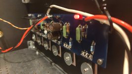
I think it'd be useful. I tried to find some labels when doing post-build trouble shooting and remember struggling to figure out where my key resistors were located once the boards were in the chassis.
Slow moving build because of work...
I try to understand the issues that Zen Mod sighted on my amplifier.
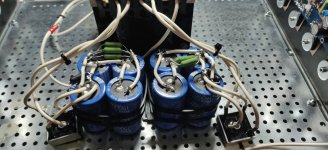
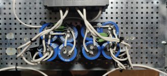
I am not sure if a change in arrangement will help or do I have to change the arrangement from a square of capacitors to a single line for every power supply. I think I haven't addressed the problem completely
ZenMod can you check if something like the photo I have posted is ok or do you think I need to change the whole arrangement? The thing that keeps me thinking is the bridges on the left and right...
Bear in mind It is not the final setup, I just moved them there to take the photo. I will fix them on the case when I am sure about the arrangement.
I try to understand the issues that Zen Mod sighted on my amplifier.
I am not sure if a change in arrangement will help or do I have to change the arrangement from a square of capacitors to a single line for every power supply. I think I haven't addressed the problem completely
ZenMod can you check if something like the photo I have posted is ok or do you think I need to change the whole arrangement? The thing that keeps me thinking is the bridges on the left and right...
Bear in mind It is not the final setup, I just moved them there to take the photo. I will fix them on the case when I am sure about the arrangement.
Attachments
I really like those!!
I will absolutely put them at the top if you like.
Of course would I like it! Glad to be able to contribute even this tiny bit.
I tried to attach the original afdesign-files, as well as the open source "Ropa" font from adobe, as zip, but this doesn't seem to work?
Last edited:
I finally got some time to try the initial power up of my F4
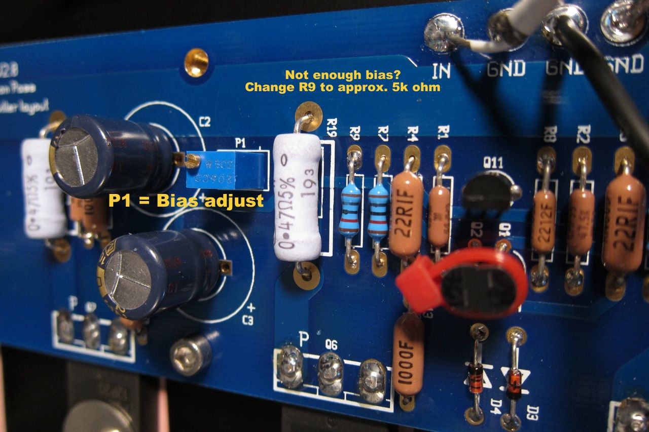
I can adjust bias and offset but the max bias I can set is 80mV across 0.47ohm resistors.
I checked R8 (22.1Kohm) and R9 (10Kohm) = they are correct, I used the NCP431ACLPRAG part for the opto .
Any ideas for what to check or should I just reduce R9/increase R8 seeing as everything else seems to be working normally.
thanks..dB
If the bias and offset pots are responding properly as you say (which is good), make R9 smaller as you suspect.
Last edited:
Thx 😀 - I thought I had seen something along this line ( and seeing the image jolted my memory that I had seen this exact post ) but after reading several pages with search, I gave up 🙂
Thanks for the guidance - 5K turned out to be too low but 6.8K was the sweet spot for this amp. Now to let it settle in and get the rest of the case work started.
I have been looking forward to hearing this particular design for a while - it would almost be like my favourite headphone amp - tube gain stage and solid state current buffer. I have high expectations and am sure it will not disappoint.
The manufacturer's name and part number are listed on the diyAudio store website.
Click on Chassis and let the page load completely.
Click on Deluxe 4U Aluminum and let the page load completely.
Scroll down to the Bold font heading: BACK PANEL
Find the hyperlink (in blue) to back panel parts kit. Click that link and let the page load completely.
There it is!! Line 2 of the Description. Manufacturer's name, part number, and link to engineering datasheet.
You can put the part number into octopart.com to find out who sells it and who has it in stock, today, ready for shipment. I did this just now (Tues 26 Jan) and found it was in stock at
- Digi-Key
- Newark
- Arrow
- Verical
- Avnet
- Mouser
- Farnell
- RS Components
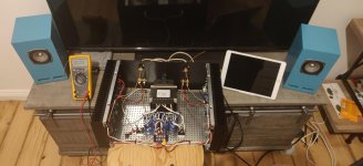
Found time and continue my build!
First thing first,
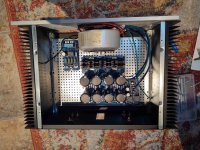
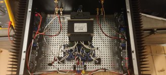
I insulated as 6L6 told and use colours for the wiring, changed Kerafoil, and moved capacitors (hope I got what ZenMod tried to explain) and now I gave a working amplifier with great help from the forum!
I attach some pictures if anyone can pinpoint anything wrong, I will make the wiring a little bit cleaner next days...
One question, I am trying to set the bias, I have maxed the potentiometer and on both channels the bias is 0.120 after one hour (it started at 0.113). Both channels the same. Do you believe there is something wrong or should I change the R9 resistors?
The potentiometers are bourns so I think they are good.
The DC offset is set to 0 +-0.2 mV
First thing first,
I insulated as 6L6 told and use colours for the wiring, changed Kerafoil, and moved capacitors (hope I got what ZenMod tried to explain) and now I gave a working amplifier with great help from the forum!
I attach some pictures if anyone can pinpoint anything wrong, I will make the wiring a little bit cleaner next days...
One question, I am trying to set the bias, I have maxed the potentiometer and on both channels the bias is 0.120 after one hour (it started at 0.113). Both channels the same. Do you believe there is something wrong or should I change the R9 resistors?
The potentiometers are bourns so I think they are good.
The DC offset is set to 0 +-0.2 mV
Attachments
Found time and continue my build!
First thing first,
I insulated as 6L6 told and use colours for the wiring, changed Kerafoil, and moved capacitors (hope I got what ZenMod tried to explain) and now I gave a working amplifier with great help from the forum!
I attach some pictures if anyone can pinpoint anything wrong, I will make the wiring a little bit cleaner next days...
One question, I am trying to set the bias, I have maxed the potentiometer and on both channels the bias is 0.120 after one hour (it started at 0.113). Both channels the same. Do you believe there is something wrong or should I change the R9 resistors?
The potentiometers are bourns so I think they are good.
The DC offset is set to 0 +-0.2 mV
Your first picture gives me vertigo! Good luck with the resistor swap. I think everyone has to do that... I have 7.5k in mine.
Ok , I will try to lower the value
This might be my next task too... To find out what value works best, you could piggyback a resistor (10K - 20K) onto R9 resulting in a perfect value... (piggybacking a resistor is easier than replacing a installed one...
Letting mine cook, should be able to hook it up to my system later

I am using Mark Johnson's soft start and Mirand Audio speaker SSR
Thanks for another great project to build !!
..dB
I am using Mark Johnson's soft start and Mirand Audio speaker SSR
Thanks for another great project to build !!
..dB
This might be my next task too... To find out what value works best, you could piggyback a resistor (10K - 20K) onto R9 resulting in a perfect value... (piggybacking a resistor is easier than replacing a installed one...
Exactly, no risk of damaging the board and with a bit of care can be added with everything in situ.
If I remember right ZM suggested paralleling R9 with 100k, and that worked well on all 4 channels on my amps
- Home
- Amplifiers
- Pass Labs
- A guide to building the Pass F4 amplifier