I've found a way to get the Coordinate Slice Points into Solidworks as a curve.
I have made a macro by hacking together some other macro code I found online. It works quite nicely so I thought I would post it here in case it is useful for anyone else.
Each file has to be imported separately which is a pain but it is in reality a few clicks per curve. Functions that can import more than one file are considerably more difficult to get working.
Instructions included in the zip file.
Macro Button Added to Toolbar
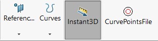
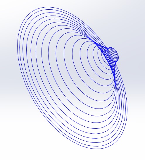
Curves
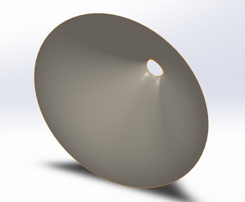
Surface Loft
I have made a macro by hacking together some other macro code I found online. It works quite nicely so I thought I would post it here in case it is useful for anyone else.
Each file has to be imported separately which is a pain but it is in reality a few clicks per curve. Functions that can import more than one file are considerably more difficult to get working.
Instructions included in the zip file.
Macro Button Added to Toolbar
Curves
Surface Loft
Attachments

This is a fully automated way of importing all the curves at once but it needs to use Excel to leverage it Multi File Selection abilities.
The macro is attached. It took me a while to work out that I needed to include the solidworks references. This will be need to be checked as each system might have different reference versions.
In the Developer tab of Excel (Hidden by Default) click the Visual Basic Button which will open the editor. Then click Tools>References
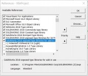
Check if the Solidworks references have been checked. Without them this code will fail. Should look something like this

Follow the instructions in the Readme from the previous posts zip attachment as they explain how to process the text files.
The code as it is here expects a new blank part to be open in solidworks. It can be made to open solidworks and make the part by uncommenting the three lines shown here. Just remove the ' from the front of the line.
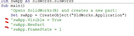
Otherwise it is as simple as pressing the Run Macro button in the sheet")
The macro is attached. It took me a while to work out that I needed to include the solidworks references. This will be need to be checked as each system might have different reference versions.
In the Developer tab of Excel (Hidden by Default) click the Visual Basic Button which will open the editor. Then click Tools>References
Check if the Solidworks references have been checked. Without them this code will fail. Should look something like this
Follow the instructions in the Readme from the previous posts zip attachment as they explain how to process the text files.
The code as it is here expects a new blank part to be open in solidworks. It can be made to open solidworks and make the part by uncommenting the three lines shown here. Just remove the ' from the front of the line.
Otherwise it is as simple as pressing the Run Macro button in the sheet
Attachments

Last edited:
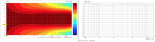
Every now and then, after changing the code, I try to re-generate and run through the whole process this horn just to check it still works as before. It still does
(This is in an infinite baffle.)
Out of cusiorsity for you use these settings for that chat chart back then? Trying to compare my version to yours.
ABEC.Polars.Step = 7.5 ; [deg]
ABEC.Polars.Points = 8
ABEC.Polars.PMapNorm = 10 ; polar map normalizing angle [deg]
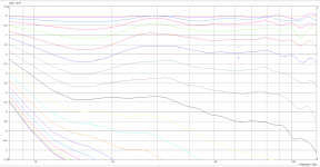
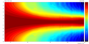
Current iteration for 1" with following ABEC settings. A few more iterations should have the curves slightly flatter, I hope.
Code:
ABEC.SimType = 1 ; infinite baffle
ABEC.f1 = 500 ; [Hz]
ABEC.f2 = 14000 ; [Hz]
ABEC.NumFrequencies = 60
ABEC.Abscissa = 2 ; 1=log | 2=linear
ABEC.MeshFrequency = 1000 ; [Hz]
ABEC.Polars.Horizontal = 1
ABEC.Polars.Vertical = 1
ABEC.Polars.Diagonal = 0
ABEC.Polars.DiagonalInclination = 0
ABEC.Polars.Dist = 2.5 ; [m]
ABEC.Polars.Step = 7.5 ; [deg]
ABEC.Polars.Points = 8
ABEC.Polars.PMapNorm = 0 ; polar map normalizing angle [deg]
Attachments
Last edited:

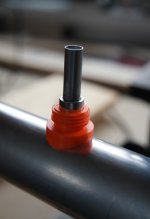
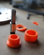
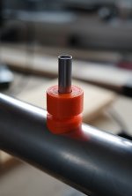
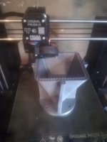
I'm making prototypes of the PWT mic mountings - this is actually my first attempt to 3d-print anything useful. I think I'm going to drill the big 8 mm holes into the tube and make it all 3d printed. It's much easier after all.

Attachments
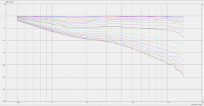
You're almost there
So close - iteration 32 zoomed. When is close good enough?
Attachments
Last edited:
Hi everyone,
First contribution on Diyaudio, I'm a long time member but only reading until today
Just wanna react about solidworks. I don't use Fusion360 I really don't like (even If I use autocad a lot, fusion360 is not for me)
So I tried to import Ath data (slicing and curve) into solidworks, and it worked perfect (after few iterations).
Here is how I do it:
- First of all configure output in my ath script
Output.Coords = yes
Output.Coords.NumProfiles = 8
Output.Coords.Scale = 1
Output.Coords.SeparateFiles = 1
Output.Coords.FileExt = txt
Then open all profiles txt files in notepad++, and remplace(Ctrl+H) ";" by Tab ("\t").
Do the same with slice txt files, but you don't need all of them. The first one and the last one are crucial (and not enough), and take some slice between this two. Remplace ";" by tabs, saves all the files.
Run solidworks, create piece.
Go to Function>Curve>Curve with XYZ coordinate (I'm not sure of the exact name since my version is in french)
Import all the files (yes It's a bit long)
Go to Surface>Lofted Surface
Select profiles for profiles (yep, logic) and slice as guide
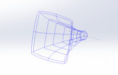
And done, now you are in a surface model.
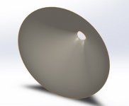
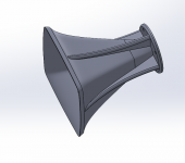
Here are some image of the waveguide I'm working on.
This prototype is printing at this exact moment
First contribution on Diyaudio, I'm a long time member but only reading until today
Just wanna react about solidworks. I don't use Fusion360 I really don't like (even If I use autocad a lot, fusion360 is not for me)
So I tried to import Ath data (slicing and curve) into solidworks, and it worked perfect (after few iterations).
Here is how I do it:
- First of all configure output in my ath script
Output.Coords = yes
Output.Coords.NumProfiles = 8
Output.Coords.Scale = 1
Output.Coords.SeparateFiles = 1
Output.Coords.FileExt = txt
Then open all profiles txt files in notepad++, and remplace(Ctrl+H) ";" by Tab ("\t").
Do the same with slice txt files, but you don't need all of them. The first one and the last one are crucial (and not enough), and take some slice between this two. Remplace ";" by tabs, saves all the files.
Run solidworks, create piece.
Go to Function>Curve>Curve with XYZ coordinate (I'm not sure of the exact name since my version is in french)
Import all the files (yes It's a bit long)
Go to Surface>Lofted Surface
Select profiles for profiles (yep, logic) and slice as guide
And done, now you are in a surface model.
Here are some image of the waveguide I'm working on.
This prototype is printing at this exact moment
Attachments
fluid, Moffrtx -
Guys, if you sum up these instructions in a form of a document, I can include it in the download package as a contributed documentation, otherwise it will just sink in the thread posts.
BTW, as you may already know, the STEP export feature remains in Fusion 360
Guys, if you sum up these instructions in a form of a document, I can include it in the download package as a contributed documentation, otherwise it will just sink in the thread posts.
BTW, as you may already know, the STEP export feature remains in Fusion 360
Last edited:
Good point, I think the Excel macro is the closest to your own script as it is mainly automated. Pretty much one click and it's done. If you wanted to add the macro into the download I can update the readme file I put in the internal solidworks macro zip into a pdf with images.fluid, Moffrtx -
Guys, if you sum up these instructions in a form of a document, I can include it in the download package as a contributed documentation, otherwise it will just sink in the thread posts.
Yes, just after I put in all the effort to get around the problemBTW, as you may already know, the STEP export feature remains in Fusion 360
Good that they listened to feedback though. Now I can keep exporting my boxes to step to import to gmsh.You're almost there
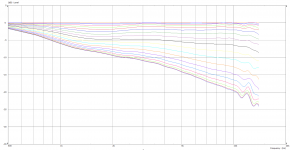
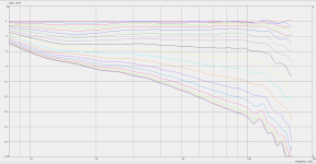
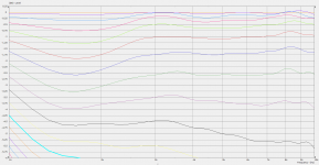
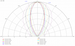
Result!
Iteration 37 is flat to +/- 0.4dB 1k to 12k, 0 to 43 degrees off axis.
Size - 15" x 11" x 108mm
Now looking at vertical dispersion / height to see I can compact the design for smaller C-to-C.
Last edited:
So show us
What I've found out is that this doesn't improve the overall performance in the end. I'm curious what your finding will be.Now looking at vertical dispersion / height to see I can compact the design for smaller C-to-C.
- Home
- Loudspeakers
- Multi-Way
- Acoustic Horn Design – The Easy Way (Ath4)