This is a concept that might work.
I would take a slightly bigger, efficient mid, with Fs < 200Hz, to keep up with the comp. driver.
Something like this (impedance could be cleaner though):
looks so promising. I think the idea is super solid!
It's nothing more than the LF extension / sensitivity / enclosure volume trade-off. You can always have only two of those at the same time, no matter what woofers you use.
There's probably some "sweet-spot" but I doubt it is anywhere above 90 dB/2.83V@m in the final sensitivity, unless you could tolerate huge enclosures.
Indeed, those are the trade-offs defined in Hoffman's Iron Law between bass extension, sensitivity (or efficiency) and (enclosure) size.
I can tolerate 200 liter enclosures.
Another misconception in the high-end scene is "fast vs slow bass". We probably all know this is related to woofer characteristics and (proper) cabinet tuning. Moreover, in my experience, high-fidelity bass reproduction primarily depends on cone surface area and excursion, and therefore efficiency.
Associated phenomena like port resonances/chuffing are hardly ever an issue when Xmax is limited to a few mm. For the same reason IM and Doppler distortion are also greatly reduced.
I assume high-quality woofers of which the motor structure, cone material and shape, as well as the suspension are properly matched.
Last edited:
Moreover, in my experience, high-fidelity bass reproduction primarily depends on cone surface area and excursion, and therefore efficiency.
I agree that volume displacement (Xmax x Sd) is a primary consideration, however, not if its all in one spot. It needs to be dispersed throughout the space.
Ideally yes, but many people can't have, or don't want 4 separate sub enclosures, including necessary amplification, cabling etc. in their (living) room.
One last (long) post dedicated to Hofmann's Iron Law, courtesy of Scott Hinson (slightly edited).
Basically the “law” states that if you are designing a speaker and looking at sensitivity, bandwidth and size, you get to pick two, and the other one is determined for you.
And it is…sounds so simple…but the devil is usually in the details as is the case here.
First a bit of history, Hofmann, is the “H” in the vaunted old school company KLH, and before that was a partner at AR. In the heyday of Hi-fi, KLH was a MAJOR player, and Hofmann was one of the firm’s founders and designers. By all accounts he was an incredibly talented engineer (having been plucked out of college to work on The Manhattan Project) and possessing a PhD from Harvard…one might assume that he knew a thing or two about physics and when he lays down an “iron law” we should probably pay attention.
From what I can tell, Dr. Josef Anton Hofmann likely proposed his law well before Thiele/Small modelling mathematics and techniques were widely circulated and understood. (Keep in mind Thiele wrote the original works a decade or so before Small refined the concept and published his papers in the Journal of Audio Engineering Society in 1972 and after.) Speakers before this time were developed using less sophisticated techniques, often with large amounts of trial and error.
The thing that Small did was provide a precise mathematical derivation for the work for both sealed and vented loudspeakers. The relationship for maximum efficiency of a sealed or vented box speaker is:
Efficiency = k x F3^3 * Vb
Where F3 = -3dB low frequency corner, or the frequency that is -3dB compared to the passband or flat frequency response region. It’s critical to note, that the efficiency Small is talking about is in the passband region, there are games to be played with using speakers in their resonant regions for efficiency, more on that later.
Vb = box volume in cubic meters.
“k” is constant scalar, for vented boxes it’s 3.9x10⁻⁶ and for sealed boxes it’s 2.0x10⁻⁶ for passive radiator boxes roughly 1x10⁻⁶. (Small, 1972) (Small, 1973) (Small, 1974)
This gives a passband efficiency which can be converted to dB SPL 2.83V 1/m (roughly) by
SPL = 112+10*log(Efficiency), where this is a base 10 logarithm.
This is theoretical maximum efficiency, in practice it’s going to be less due to mechanical losses in the box, ports (if present) and box leakage. Notice that the only inputs to these formulas are box size, F3 and efficiency…the driver parameters are rolled into the constant scalar k. But the constant is just that…the same…which means that the box volume and desired F3 are the critical factors in efficiency.
Let me repeat that for emphasis: if you know what F3 you want to hit, and your efficiency, your box size has been pre-determined for you no matter what driver you pick. Magnet size, dual voice coil, cone material, or marketing materials from the company manufacturing the sub can’t exceed this limit. If you’re looking at a commercial sub box you can estimate its internal volume and double check the claims for sensitivity and low frequency performance.
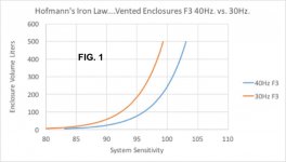
Now….let’s look at a real world example: if I am looking at subs with two different F3’s, and want to compare efficiency and volume the graph looks like figure 1. Notice how fast the boxes get big.
Now, there are some corollary rules for Hofmann’s Iron law…let’s examine those.
1. If you have a high excursion driver, make sure that you can make use of the excursion without hitting thermal limits. This is typically a problem for the mega home theater subs and car audio woofers with very high xmax. They are designed to be low efficiency drivers to gain bandwidth. If your woofer takes 4000w to hit xmax but only handles 1000w thermal, you won’t be reaching xmax very often.
2. If you’ve managed to get high sensitivity and a relatively low F3 out of a driver make sure it can handle excursion. This is typically a problem for PA drivers used to achieve ultra low F3’s in vented alignments. I support choosing a good Extended Bass Shelf (EBS) type alignment with these drivers, but it must be done with proper high pass filtering when used at high volumes. It’s not uncommon for a 500w PA driver to be excursion-limited to less than 100w power handling in an inappropriate cabinet.
3. If you think you’ve managed to break the law, you haven’t…the iron law still effectively holds with horn speakers and higher order (bandpass subs, etc) in the form of bandwidth vs efficiency tradeoff. In many cases you’ve created a very narrow bandwidth box and you’ve gotten to the efficiency using resonance at the expense of time domain accuracy since all those resonant structures will continue to resonate for a very long time after the input signal disappears.
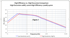
So let’s look at an example…I did some modeling using two 18” sealed subwoofers. One using a high excursion home theater woofer and the other using a pro-sound woofer.
The home theater driver was simulated with a 90L enclosure with an F3 of roughly 33Hz, and is rated for 1000W power handling and an xmax of 22mm. The PA driver was in a 160L with an F3 of roughly 60Hz, and is rated for 1700W power handling and an xmax of 14mm.
In the flat passband of both drivers say 100Hz or so, you could get the home theater style driver to equal the output of the PA speaker, but you’d need over 10kW to do it and the driver would likely not last too long.
Within both drivers thermal limits the home theater subwoofer easily outpaces the pro woofer at low frequencies, but Hofmann being correct the PA driver easily beats the home theater sub at higher frequencies.
But let’s look at the corollaries. For corollary number 1, if you are pushing that high excursion driver it has the excursion to keep up with the PA output, but it can’t keep up thermally. In order to come close it has to have over 10kW of power applied. (The simulator limited me to a 10kW input.) In all likelihood the driver will be damaged…and even if it’s not, thermal compression would mean that it won’t even get as close as Figure 1.
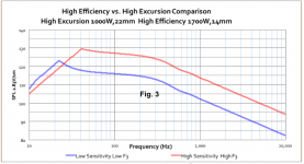
Now let’s look at corollary 2….this time both woofers are kept at within thermal ratings. If you look at the red plot in Figure 3, which is the high sensitivity PA woofer notice that at 100Hz the output curve takes a sharp dive. This is where the woofer becomes excursion limited…meaning you there will be higher distortion and eventually damage if you start to push past this point. The high excursion driver eventually starts beating the pro driver for output but it doesn’t happen until between 40Hz and 60Hz, and that driver quickly becomes excursion limited, as shown by the sharp knee in the plot.
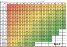
Lastly I’ve created two tables for you, one for sealed systems and one for vented (Table 1 and Table 2). This plots F3 and Box size on columns and rows, and has the corresponding maximum efficiency. It’s worthwhile noting at this point that this is pass band efficiency (the flat-ish section of the frequency response plots your simulators spit out), where there is little back EMF from the driver structure, and the driver is assumed to be 8 ohms. If the driver is less than 8 ohms you’ll need to add 10*log(8/Re) of the driver where Re is the DC resistance of the voice coil to achieve the sensitivity rating for that driver in that box.
One final thing to note, I’ve been very careful to try and maintain consistency with the terms efficiency and sensitivity.
Efficiency is a ratio of acoustical power out of a speaker to electrical power into a speaker. This is what the formulas in Small’s papers address. Sensitivity is the sound pressure level at a given distance for a given input voltage in volts RMS.
The reason I bring this up is because there are quite a few examples of subwoofer systems where designers pack a large high excursion driver into a tiny box, often with a passive radiator. People use these systems as examples of violations of Hofmann’s Iron Law….they’re not.
Dr. Small references passband efficiency or the efficiency in the region where the driver was operating with flat frequency response as a piston. Taken in historical context the systems he was designing were using the driver as the woofer in a two way or three way loudspeaker. With these very tiny subwoofers (or even bandpass subwoofers) there is no real passband, or level frequency response region. The manufacturer of these super small cabinets is making use of the fact that the subwoofer will be used over a very narrow frequency range, outside of the passband. If you tried to drive these systems to their passband region, if you can find one, you would see that efficiency is quite low. Iron law maintained.
Bibliography
Small, R. (1972). Closed Box Loudspeaker Systems Part 1: Analysis (Vol. 20). The Journal of the Audio Engineering Society.
Small, R. (1973). Vented-Box Loudspeaker Systems (Vol. 21). The Journal of the Audio Engineering Society.
Small, R. (1974). Passive-Radiator Loudspeaker Systems Part 1: Analysis (Vol. 22). The Journal of the Audio Engineering Society.
Basically the “law” states that if you are designing a speaker and looking at sensitivity, bandwidth and size, you get to pick two, and the other one is determined for you.
And it is…sounds so simple…but the devil is usually in the details as is the case here.
First a bit of history, Hofmann, is the “H” in the vaunted old school company KLH, and before that was a partner at AR. In the heyday of Hi-fi, KLH was a MAJOR player, and Hofmann was one of the firm’s founders and designers. By all accounts he was an incredibly talented engineer (having been plucked out of college to work on The Manhattan Project) and possessing a PhD from Harvard…one might assume that he knew a thing or two about physics and when he lays down an “iron law” we should probably pay attention.
From what I can tell, Dr. Josef Anton Hofmann likely proposed his law well before Thiele/Small modelling mathematics and techniques were widely circulated and understood. (Keep in mind Thiele wrote the original works a decade or so before Small refined the concept and published his papers in the Journal of Audio Engineering Society in 1972 and after.) Speakers before this time were developed using less sophisticated techniques, often with large amounts of trial and error.
The thing that Small did was provide a precise mathematical derivation for the work for both sealed and vented loudspeakers. The relationship for maximum efficiency of a sealed or vented box speaker is:
Efficiency = k x F3^3 * Vb
Where F3 = -3dB low frequency corner, or the frequency that is -3dB compared to the passband or flat frequency response region. It’s critical to note, that the efficiency Small is talking about is in the passband region, there are games to be played with using speakers in their resonant regions for efficiency, more on that later.
Vb = box volume in cubic meters.
“k” is constant scalar, for vented boxes it’s 3.9x10⁻⁶ and for sealed boxes it’s 2.0x10⁻⁶ for passive radiator boxes roughly 1x10⁻⁶. (Small, 1972) (Small, 1973) (Small, 1974)
This gives a passband efficiency which can be converted to dB SPL 2.83V 1/m (roughly) by
SPL = 112+10*log(Efficiency), where this is a base 10 logarithm.
This is theoretical maximum efficiency, in practice it’s going to be less due to mechanical losses in the box, ports (if present) and box leakage. Notice that the only inputs to these formulas are box size, F3 and efficiency…the driver parameters are rolled into the constant scalar k. But the constant is just that…the same…which means that the box volume and desired F3 are the critical factors in efficiency.
Let me repeat that for emphasis: if you know what F3 you want to hit, and your efficiency, your box size has been pre-determined for you no matter what driver you pick. Magnet size, dual voice coil, cone material, or marketing materials from the company manufacturing the sub can’t exceed this limit. If you’re looking at a commercial sub box you can estimate its internal volume and double check the claims for sensitivity and low frequency performance.
Now….let’s look at a real world example: if I am looking at subs with two different F3’s, and want to compare efficiency and volume the graph looks like figure 1. Notice how fast the boxes get big.
Now, there are some corollary rules for Hofmann’s Iron law…let’s examine those.
1. If you have a high excursion driver, make sure that you can make use of the excursion without hitting thermal limits. This is typically a problem for the mega home theater subs and car audio woofers with very high xmax. They are designed to be low efficiency drivers to gain bandwidth. If your woofer takes 4000w to hit xmax but only handles 1000w thermal, you won’t be reaching xmax very often.
2. If you’ve managed to get high sensitivity and a relatively low F3 out of a driver make sure it can handle excursion. This is typically a problem for PA drivers used to achieve ultra low F3’s in vented alignments. I support choosing a good Extended Bass Shelf (EBS) type alignment with these drivers, but it must be done with proper high pass filtering when used at high volumes. It’s not uncommon for a 500w PA driver to be excursion-limited to less than 100w power handling in an inappropriate cabinet.
3. If you think you’ve managed to break the law, you haven’t…the iron law still effectively holds with horn speakers and higher order (bandpass subs, etc) in the form of bandwidth vs efficiency tradeoff. In many cases you’ve created a very narrow bandwidth box and you’ve gotten to the efficiency using resonance at the expense of time domain accuracy since all those resonant structures will continue to resonate for a very long time after the input signal disappears.
So let’s look at an example…I did some modeling using two 18” sealed subwoofers. One using a high excursion home theater woofer and the other using a pro-sound woofer.
The home theater driver was simulated with a 90L enclosure with an F3 of roughly 33Hz, and is rated for 1000W power handling and an xmax of 22mm. The PA driver was in a 160L with an F3 of roughly 60Hz, and is rated for 1700W power handling and an xmax of 14mm.
In the flat passband of both drivers say 100Hz or so, you could get the home theater style driver to equal the output of the PA speaker, but you’d need over 10kW to do it and the driver would likely not last too long.
Within both drivers thermal limits the home theater subwoofer easily outpaces the pro woofer at low frequencies, but Hofmann being correct the PA driver easily beats the home theater sub at higher frequencies.
But let’s look at the corollaries. For corollary number 1, if you are pushing that high excursion driver it has the excursion to keep up with the PA output, but it can’t keep up thermally. In order to come close it has to have over 10kW of power applied. (The simulator limited me to a 10kW input.) In all likelihood the driver will be damaged…and even if it’s not, thermal compression would mean that it won’t even get as close as Figure 1.
Now let’s look at corollary 2….this time both woofers are kept at within thermal ratings. If you look at the red plot in Figure 3, which is the high sensitivity PA woofer notice that at 100Hz the output curve takes a sharp dive. This is where the woofer becomes excursion limited…meaning you there will be higher distortion and eventually damage if you start to push past this point. The high excursion driver eventually starts beating the pro driver for output but it doesn’t happen until between 40Hz and 60Hz, and that driver quickly becomes excursion limited, as shown by the sharp knee in the plot.
Lastly I’ve created two tables for you, one for sealed systems and one for vented (Table 1 and Table 2). This plots F3 and Box size on columns and rows, and has the corresponding maximum efficiency. It’s worthwhile noting at this point that this is pass band efficiency (the flat-ish section of the frequency response plots your simulators spit out), where there is little back EMF from the driver structure, and the driver is assumed to be 8 ohms. If the driver is less than 8 ohms you’ll need to add 10*log(8/Re) of the driver where Re is the DC resistance of the voice coil to achieve the sensitivity rating for that driver in that box.
One final thing to note, I’ve been very careful to try and maintain consistency with the terms efficiency and sensitivity.
Efficiency is a ratio of acoustical power out of a speaker to electrical power into a speaker. This is what the formulas in Small’s papers address. Sensitivity is the sound pressure level at a given distance for a given input voltage in volts RMS.
The reason I bring this up is because there are quite a few examples of subwoofer systems where designers pack a large high excursion driver into a tiny box, often with a passive radiator. People use these systems as examples of violations of Hofmann’s Iron Law….they’re not.
Dr. Small references passband efficiency or the efficiency in the region where the driver was operating with flat frequency response as a piston. Taken in historical context the systems he was designing were using the driver as the woofer in a two way or three way loudspeaker. With these very tiny subwoofers (or even bandpass subwoofers) there is no real passband, or level frequency response region. The manufacturer of these super small cabinets is making use of the fact that the subwoofer will be used over a very narrow frequency range, outside of the passband. If you tried to drive these systems to their passband region, if you can find one, you would see that efficiency is quite low. Iron law maintained.
Bibliography
Small, R. (1972). Closed Box Loudspeaker Systems Part 1: Analysis (Vol. 20). The Journal of the Audio Engineering Society.
Small, R. (1973). Vented-Box Loudspeaker Systems (Vol. 21). The Journal of the Audio Engineering Society.
Small, R. (1974). Passive-Radiator Loudspeaker Systems Part 1: Analysis (Vol. 22). The Journal of the Audio Engineering Society.
Attachments

Last edited:
Associated phenomena like port resonances/chuffing are hardly ever an issue when Xmax is limited to a few mm.
Can you explain this? These are unrelated to each other in any standardized scenario, are they not?
Ideally yes, but many people can't have, or don't want 4 separate sub enclosures, including necessary amplification, cabling etc. in their (living) room.
Why quote numbers? It's not about that. It's about having more than one, one is a bad idea.
Why quote numbers? It's not about that. It's about having more than one, one is a bad idea.
Not in my experience, as it depends on the room.
Two paths, maximize modes (multiple subs)
Or minimize modes, single sub in corner.
Depends on the room....
I understand all the advantages of the multi-sub system design and acknowledge they can be substantial. At the moment for me it's just too much hassle, simple as that.
Last edited:
Can you explain this? These are unrelated to each other in any standardized scenario, are they not?
Yes, but not quite in the scenario of a large ported enclosure with a big, properly constructed, low Xmax woofer (= less prone to Doppler distortion) that isn't tuned way below Fs (the excess excursion is a major source of IMD).
It remains an impressive phenomenon; with barely more than 1 Watt output, the cones hardly seem to move, while in the kitchen (10 - 12 meters away) the glassware is ringing.
Last edited:
Whether or not ringing glassware is a reliable indicator for high quality sound reproduction I'm not entirely convinced. ;-)
Anyway, long time lurker here, I've been following this thread with great interest! But obviously I have not read every post or simply can't remember. So why was the waveguide-in-a-baffle approach abandoned? What mabat I believe called the Tritonia and even posted waveguide-baffles routed from solid MDF to me was much more interesting than all this freestanding stuff.
Both for aesthetic (such "look at me" horn speakers always make me think of 'audiophile' dentists (no offense) who are about to strangle you with their 1000$ cables) and practical reasons (I run a little post production studio and rectangular boxes are just much easier to handle / integrate in a room filled with technology and much less visually distracting).
I understand there might be slight advantages of having the waveguide freestanding diffraction-wise, but they seem to be very small and personally I would also prefer a non-symmetrical waveguide (while being fully aware of the disadvantages), even more so than the Tritonia. Were there substantial technical reasons for abandoning that approach?
Last edited:
I read through the posts where that was discussed and it was a real shame that it came to [nada]...
DIY Klippel would be truly awesome. I have virtually no maths skill...but if I could help in any way I would.
There is a new push to do this over at ASR that you could probably contribute to, your ABEC work shows plenty of skill.
The main man for the maths is modest but pretty impressive, is well ahead of what was done in the DIY thread and where I had reached.
Someone has started to work on a CNC mechanism but that part looks less impressive to me.
Actually I think it looks ill conceived but I have held off any criticism until I can show a proposal that's (possibly) better.
Time to learn FreeCAD.
Best wishes
David
Whether or not ringing glassware is a reliable indicator for high quality sound reproduction I'm not entirely convinced. ;-)
It's not, of course. It's just a by-product of highly efficient big woofers 🙂
Speaking of ASR, in this thread some misconceptions regarding bass reflex (ringing, phase-shift etc.) are debunked.
Your own personal circumstances or preferences are valid reasons to choose another option but perhaps the results of the simulations I did linked below will illustrate why there is a tangible advantageI understand there might be slight advantages of having the waveguide freestanding diffraction-wise.... Were there substantial technical reasons for abandoning that approach?
Here is a simulation comparing an infinite baffle terminated waveguide and then the same guide with a woofer underneath as non driven surface
2 way waveguide speaker build ABEC modelling
Freestanding with Woofer and cabinet underneath freespace
2 way waveguide speaker build ABEC modelling
Your own personal circumstances or preferences are valid reasons to choose another option but perhaps the results of the simulations I did linked below will illustrate why there is a tangible advantage
Here is a simulation comparing an infinite baffle terminated waveguide and then the same guide with a woofer underneath as non driven surface
2 way waveguide speaker build ABEC modelling
Freestanding with Woofer and cabinet underneath freespace
2 way waveguide speaker build ABEC modelling
That is interesting. There's just so many balls to juggle, I find it hard to separate the influence of all the variables to find the compromise one is willing to accept. In this case for example: if the waveguide had its own enclosure, basically terminating into a rectangular box with proper roundovers and you would move that box forwards and backwards on top of the woofer box - what would happen? How far does the waveguide mouth have to be removed from the baffle to separate (so to speak) the dispersion patterns?
@Marcel
In my sim parameters I changed the lower limit to twenty Hz, but the graph only goes down to default 200, can I change that?
By the way how does this look for a HF1440 large format horn?

In my sim parameters I changed the lower limit to twenty Hz, but the graph only goes down to default 200, can I change that?
By the way how does this look for a HF1440 large format horn?
Last edited:
What it shows is the effect on diffraction and response from nearby objects. If you are targeting a reduction in diffraction and a consistent polar response over as large a range as possible it is interesting. If you believe that an improved anechoic response leads to an improved listening position response it is interesting. Otherwise it probably means nothing.It's all dandy and fine, what does it mean at listening position?
I don't know the answer to that, what I do know is that finding the best balance of width, depth and roundover on a flat baffle is much more difficult than you might imagine and the simulations needed are very time consuming due to the size of the models needed. Finding a way to incorporate the rollbackIn this case for example: if the waveguide had its own enclosure, basically terminating into a rectangular box with proper roundovers and you would move that box forwards and backwards on top of the woofer box - what would happen?
Far enough that the CTC distance starts to be become impractical for any workable crossover.How far does the waveguide mouth have to be removed from the baffle to separate (so to speak) the dispersion patterns?
- Home
- Loudspeakers
- Multi-Way
- Acoustic Horn Design – The Easy Way (Ath4)