Interesting! Wasn't aware that 'cutoff' isn't well defined in horn design in that the various engineering markets I've worked in it always means the product's design limits at some preset value.
Same hear but as a hobbyist. All the horn's I have used have always had a lowest recommended crossover or useable low frequency limits or simply cutoff on the data sheets. The use of the term "tuning note" just confuses the conversation IMHO.
Rob🙂
Last edited:
I think that we all think of different things when we think "cutoff". The point is to be clear what we mean by that. 1/2 power is a norm, but that's not consistent with it's usage in "horn" theory (and some physics) where it means complete shutoff of output. Very different things.
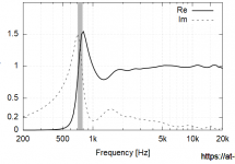
The 1/2 power of the above would be at 660+- Hz. Since there is output, then this can be the only applicable definition of cutoff in this case.
The 1/2 power of the above would be at 660+- Hz. Since there is output, then this can be the only applicable definition of cutoff in this case.
Last edited:
Well at least we agree. I know am concerned about a horn builders definition when thousands of dollars are at hand...
Sometimes by putting up a number, implying cutoff without saying the words, "cutoff" lets one get away with murder...then again, without being totally specific about what one means by it, it, can essentially mean anything.
Sometimes by putting up a number, implying cutoff without saying the words, "cutoff" lets one get away with murder...then again, without being totally specific about what one means by it, it, can essentially mean anything.
Attachments

Last edited:
But You are saying that you can't think of any horns where the point on the above graph is not apparent?
Well, the impedance spike as Dr. Geddes noted.
"Full loading to 400hz", it says......IN my mind there is no full loading past the point where acoustic impedance peaks...it falls off above or below this point depending on Q of the peak but below, it seems to fall off most, in my research.....Potentially the drivers F is a factor but looking at the graph above I would think that this horn cutoff is where I highlighted....why am I wrong? I guess I should look at this as old data maybe not governed in the light of the ideas we have now? I just know there is a group delay bump in there but maybe its just a small one...
Attachments

Hmm, OK, you've shown us one where the horn has damped the driver to a bit below its Fs as shown by the rising impedance double hump, so almost as good as it gets.
Cutoff in a conical is even more of a hopeless description than when applied to OS. Here is a pretty big 50x50 modelled after the SH50.Don't know....Marks experience with his horn, can't trust it without confirmed horn cutoff data.
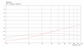
This is the radiation impedance the scale only goes down to 1K because it is already at virtually nothing by then. Apart from concentrating the radiation into a smaller space there is not much help from a flat sided horn. Real = Imaginary at about 3.4K. A secondary flare hardly changes the Rad Imp at all, it does a lot for directivity though.
Overkill and more is more are always popular in DIY. If one is good 20 must be amazing.I guess you could say I am attempting to investigate, properly, the specs of this driver. Mark100 had an interesting philosophy towards amps that I've applied to horn.
So here I wouldn't use a horn smaller than what the Driver is specified for, which is to 300hz, which implies a 150hz horn or bigger to so properly, at least in a very strict approach....simply to know that I have the drivers full bandwidth available.
Always a trade off. Simply a matter of choosing which one you want to go with, no one is a loser.
You have to be careful in oversizing or overrating things for the sake of it without understanding why it might be a good idea or a bad one. It is easy to make a virtually perfect amplifier at very low power outputs, it becomes increasingly hard to do so as you raise the power output needed. If you achieve it, it comes at the cost of expense, size, heat, noise or something else.
When you build a PA system and listen to it at 5m plus the chance of hearing hiss from an amplifier is very low. When you put a sensitive compression driver in a horn a listen to in an active system at 1m you will most likely be looking for ways to reduce the hiss.
Making a horn bigger than it needs to be for the use case might end up in the same category.
Attachments
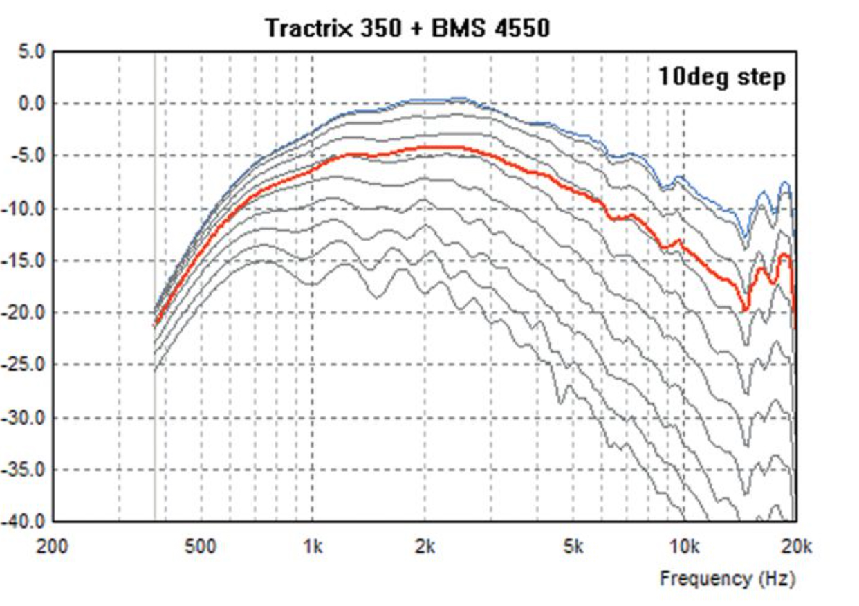
A number of pages ago i said i'd look for impedance traces of the me464. Found i didn't have any so just now made some .
Here's the lower section of the dcx464 CD, first with no horn and then on the me464 horn.


Here's the same thing with the bms4594HE.
CD lower section no horn, then on the me464.


Here's two more horns with the bms just for comparisons....sorry don't have the horns for the dcx too.
bms 4594he lower section on XT1464 (in a box with very small baffle)

And last, bms on current syn9 75x60 conical horn.
It's similarity to the CD without a horn illustrates fluids last post i think

Here's the lower section of the dcx464 CD, first with no horn and then on the me464 horn.
Here's the same thing with the bms4594HE.
CD lower section no horn, then on the me464.
Here's two more horns with the bms just for comparisons....sorry don't have the horns for the dcx too.
bms 4594he lower section on XT1464 (in a box with very small baffle)
And last, bms on current syn9 75x60 conical horn.
It's similarity to the CD without a horn illustrates fluids last post i think
I knew Mark was a real one! =) thank you so much for coming through with measurements!
First controversial statement...
That is NOT a 150hz horn....is NOT good at 300hz...
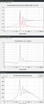
That horn is tuned to 400hz...and group delay should confirm....max resistance/reactance is at ~400hz....measure GD on horn with no filter for nail in coffin.
Boom
First controversial statement...
That is NOT a 150hz horn....is NOT good at 300hz...
That horn is tuned to 400hz...and group delay should confirm....max resistance/reactance is at ~400hz....measure GD on horn with no filter for nail in coffin.
Boom
Last edited:
lol on this page maybe 🙂First controversial statement...
B&C says it loads to 300 Hz and I see nothing in there to doubt them. The raw impedance of the dcx has a lower peak of 400Hz in free air that moves to 300 and is damped quite a lot on the ME464.That is NOT a 150hz horn....is NOT good at 300hz...
That horn is tuned to 400hz...and group delay should confirm....max resistance/reactance is at ~400hz....measure GD on horn with no filter for nail in coffin.
Boom
You should be looking to the impedance troughs, not the peaks. Loading lowers excursion and thus electrical impedance.
Maybe you should should learn how to read and interpret the graphs you are asking for.You should be looking to the impedance troughs, not the peaks. Loading lowers excursion and thus electrical impedance.
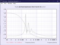
Excursion super imposed over impedance.You should be looking to the impedance troughs, not the peaks. Loading lowers excursion and thus electrical impedance.
lolMaybe you... should should learn how to read and interpret the graphs....
The peak of acoustic impedance is riiiight there, its not directly on the dip in excursion but its really really close.
Attachments

Last edited:
Excursion super imposed over impedance.
Try again.
You'll have to explain what you think you see here that has any relevance to mark's measurements.
.max resistance/reactance is at ~400hz....measure GD on horn with no filter
At the tuning note, at the fundamental, at the root mode, at max resonance etc etc etc
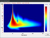
Group Delay peaks...Pressure Peaks.... I've said this stuff before, I wonder if its been passed off as "my crazy theories"....maybe pay attention to horn resp more? I described group delay (in a horn) as a function of pressure on the diaphragm, causing the diaphragm to lag behind. Another one of my crazy theories? Maybe....

I also said that excess decay can be found here...
Non of these things are good for Sound Quality I said.
Attachments
Last edited:
At the tuning note, at the fundamental, at the root mode, at max resonance etc etc etc
Group Delay peaks...Pressure Peaks.... I've said this stuff before, I wonder if its been passed off as "my crazy theories"....maybe pay attention to horn resp more? I described group delay (in a horn) as a function of pressure on the diaphragm, causing the diaphragm to lag behind. Another one of my crazy theories? Maybe....
OK so you can't explain it because you don't understand it. These horns you show with the horrible impedance and group delay are examples of how not to build a horn. Your current attitude is at an all time low. This feels like arguing which I have no interest in.
- Home
- Loudspeakers
- Multi-Way
- Is it possible to cover the whole spectrum, high SPL, low distortion with a 2-way?