You would have to explain to me what that means. Or even better, show me the profile you are interested in on a grid and I'll approxiate it with the OS-SE formula - that's what I can handle. Who needs all the other profile "types"...Mabat thanks for throwing me a bone....if you would go even more extreme placing the fundamental mode where it would be located with the average 200hz horn that would be more relevant to my experiment idea....
Edit time over. I think a MEH would yield best system overall, but have no resources (time) to prototype one yet and the simulations are hard. I've tried to persuade capable people to sim the effect of the MEH mid taps have on otherwise good performing waveguide / horn but no success yet 😀 Until then I'll experiment with what I have. Also following your progress, mark100.
" I might end up with big high sensitivity system some day and then I'll eat my words but for now big high sensitivity system seems unnecessary with high cost, big size and no benefit audio performance wise in living room situation."
Hello tmuikku
You should try at some point if for no other reason than you will have a great time just going through the process of putting the system together and tuning it in. They don't have to be huge. A 15" and a large format driver can easily fit in a 2X2 ft. footprint with a 95/98 dB @ 1 meter. Not the highest sensitivity but high enough compared to your typical systems in the upper 80s-90 db.
Rob 🙂
Yes, current setup is 3-way with 15" bass 😀 and it is a lot of fun but I plan to experiment smaller mains at some point. Subwoofer system is also on the radar. I believe the mains size can be reduced considerably with subwoofer system. My ideal system would be excellent sound without being an eyesore, speakers need to be big enough but not any bigger.
I'm no expert on horns, but this seems to be the subject of debate. If loading was something one could tune more or less without affecting the pattern control there would be no debate I reason. HOMs are mentioned, but I don't comment on that because I don't know much about it. Constant directivity is something I understand and appreciate.
I've played with the ATH sims guite many hours and manage to get very smooth looking graphs without diffraction and the loading is something that seems to be the trade-off for this smoothness. Consequently the pattern is rather wide, it is hard if not impossible to tune in constant high DI without issues in the response graphs. Trading off the loading seems to be worth it since there is plenty of sensitivity for home system. I can't comment yet if I prefer higher or lower DI, higher DI would make more sense to eliminate the room as much as possible which I can't treat acoustically (living room) but then I see problems to integrate with the woofer system below so I'm very fine with a bit lower constant DI without any issues, actually can't hope for more for a home system. Except no HOMs, small size, cheap price. ;D
On the ATH sims you've run, does a higher DI come from a larger diameter mouth, or from changing the rate of expansion?
I would think expansion rate (or the correct term) that equates to wall angle in a conical, controls DI.
And mouth diameter primarily controls how low pattern control extends.
I'm led to believe mouth diameter doesn't effect loading until the horn is at a minimum 1/4 wL long, and really needs to be 1/2 WL long.
Just my horn-novice take again, wondering how that fits with your sims...???
For the short history of home speaker DIY I've had the loading seems to be something not to worry about, it provides sensitivity that I wouldn't need. If it was tunable I'd tune it so that I wouldn't have to use a pad, but the pad is only a gain knob or two resistors so I just don't care about it 🙂 If the system sensitivity needs to be very high then it is a serious problem, to keep the high sensitivity, loading is a must I think, but this would be very big system and there is no need for such thing at home. I take the high sensitivity as valuable asset since I can sacrifice some of it as trade-off to something else.
I don't think about CD loading either...even for PA. Don't want to use a CD so low it needs loading.
I do give lowest freq of pattern control a lot of consideration though. I think this rocks, even indoors. Stinking size matters Lol
Everyone got their own desires and goals. I might end up with big high sensitivity system some day and then I'll eat my words but for now big high sensitivity system seems unnecessary with high cost, big size and no benefit audio performance wise in living room situation. Mind you I'm still exploring what is good sound and good system so eating some words is expected in the long term at least 😀
Amen ! Let's all keep exploring, doing whatever works for us, and HAVE FUN doing it 😀
Dr. Geddes,
Could you please elaborate on the reasons, results, and the like?
When a compression driver is placed on a "true" CD waveguide, the response on axis will fall at 6 dB/oct after the "mass break point" - which is another way of saying "resonance" or the low end. SO a CD waveguide is falling over most of its bandwidth. A 1st order HP filter at about 10 kHz will thus make the system flat in the passband, with a 3rd order HP at the waveguides "cutoff". Some tailoring of broad ripples in the pass band from the drivers resonance and the front chamber resonance need to be done with some parallel tank circuits, but the basic shape of the X-over filter is that of a 1st order HP at 10 kHz. In the end we have a very nice 3rd order HP down near the waveguide cutoff.
I would think expansion rate (or the correct term) that equates to wall angle in a conical, controls DI.
It would probably be more correct to state that DI, expansion rate, mouth size and flare are all "coupled" in the sense that changing any one tends to change coverage angle and slope of DI in complex way's. It's not simply that one does one thing and the other another thing.
Dr. Geddes,
thank you for your explanation. Yes, I remember that you did mention that your particular combination of driver/wave-guide had several resonances.
Kindest regards,
M
thank you for your explanation. Yes, I remember that you did mention that your particular combination of driver/wave-guide had several resonances.
Kindest regards,
M
All drivers and horns will have these resonances, they are part of the basic system of a compression driver. In fact changing drivers only ever requires a tweaking of the resonance parameters - they all have them.
Dr. Geddes,
Yes, I had seen this in measurements.
Kindest regards,
M
All drivers and horns will have these resonances, they are part of the basic system of a compression driver.
Yes, I had seen this in measurements.
Kindest regards,
M
Yes, current setup is 3-way with 15" bass 😀 and it is a lot of fun but I plan to experiment smaller mains at some point. Subwoofer system is also on the radar. I believe the mains size can be reduced considerably with subwoofer system. My ideal system would be excellent sound without being an eyesore, speakers need to be big enough but not any bigger.
Hello tmuikku
I agree subs can have a significant effect on mains size. The reduction in cabinet size can be significant. My larger systems are in the den and basement. In my living room I have a pair of Revel Performa f 206's with a sub. Much easier to integrate size wise and easier on the eye. Also a fine system in it's own right. Best of luck have fun doing it!
Rob 🙂
Indeed! A driver's diaphragm size based on its mean BW for a 20-120 Hz woofer ideally requires a ~ 89" diameter diaphragm, but a single ~ full-range 120-20 kHz driver only has to have a ~ 2.783" diaphragm to be acoustic power balanced 20-20 kHz!
Bob,is this a good article for someone who knows nothing of horn design to learn from? https://www.grc.com/acoustics/an-introduction-to-horn-theory.pdf
I ask because I’d hate to take the time to read and understand something quite complicated and find out later it’s wrong!
I’m trying to follow this thread as I find it quite interesting but need more education to keep up!
Yes, it is a very good article to learn from.
If you read and understood the concepts expressed in it, you will have the education to understand the associations between different types of horn designs and their loading, cutoff, and directivity index versus frequency and the frustration of those who have repeatedly explained those concepts multiple times throughout this endless thread.
Each time I open this thread, I'm reminded of Yogi Berra saying: “It’s like déjà vu all over again.”😀
Still, I do find it more fun than watching baseball...
Art
On the ATH sims you've run, does a higher DI come from a larger diameter mouth, or from changing the rate of expansion?
I would think expansion rate (or the correct term) that equates to wall angle in a conical, controls DI.
And mouth diameter primarily controls how low pattern control extends.
I'm led to believe mouth diameter doesn't effect loading until the horn is at a minimum 1/4 wL long, and really needs to be 1/2 WL long.
Just my horn-novice take again, wondering how that fits with your sims...???
Amen ! Let's all keep exploring, doing whatever works for us, and HAVE FUN doing it 😀
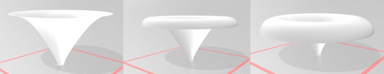
I don't remember 😀 I tried to look the data and found out I've been very poor archiving things. Found an interesting GIF though and the associated models as well. It seems to be a test how mouth rollback start parameter affects things in the ATH model. Depth and angle in the configuration file is 20cm and 33 degrees for all. Random-0 is some random settings without rollback, random-50 has rollback starting 50% of the profile length and the random-80 is starting at 20%.
Many things can be observed from this particular set:
- mouth rollback removes the resonances, but also makes the DI rising with frequency.
- The impedance/loading stays pretty much the same.
- Overall depth reduces with the rollback, first one being 20cm deep, last one ~14cm deep.
- The pattern is quite narrow and DI is "flat" only without rollback.
- Overall diameter on all these is about 14" give or take and the initial profile stays about the same until rollback kicks in.
- Bigger rollback smoothens the response very nicely.
The impedance doesn't seem to be affected by the changing depth. DI is rising with frequency with rollback, in fact the high frequency DI stays about the same but the low frequency DI drops with rollback, reduced depth or does the effective mouth size reduce with the rollback? Profile before rollback and overall mouth diameter both stay about the same on all variations. So the impedance is probably related to "the expansion", profile before rollback? Does this fit your model? I haven't thought about it, just playing with the simulations.
Anyway, in this case the impedance and "beaming" seems to not be related and perhaps can be tuned separately? I mean the beaming as rising DI since this particular model is as narrow dispersion as defined in the script.
Alright, lets do another test, I'll try increase the depth parameter which makes huge horn and we should see the impedance stay about the same and pattern control lower!? This is exciting, having loads of fun 🙂 Give me some time to prep this
Attachments

Last edited:
Each time I open this thread, I'm reminded of Yogi Berra saying: “It’s like déjà vu all over again.”😀
Still, I do find it more fun than watching baseball...
....and many others over the decades. 🙁
+1 among some other sports. 😉
Last edited:
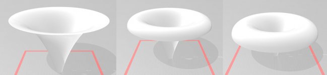
Okay same scripts but length = depth parameter changed from 200mm to 400mm and plot is from 400Hz up instead of 800Hz up in the previous.
Overall diameter varies 28"-29" give or take. Depths are 40cm, ~34cm and 28cm.
I don't know how the script uses the rollback start parameter, here the rollback start are 50% and 20% of the profile length as well, but it looks like much less on the models, don't know why is this. Profile, or expansion, should be the same since the profile defining variables wasn't changed here?
Amazingly the impedance is pretty much the same as with the lot smaller device 😀 so, it looks like the impedance can be changed at will rather independently of the other general aspects of the device (depth and mouth size), the pattern control.
Question then becomes can the pattern be varied at will if loading extends lower in frequency and can it be smoothed out? Already the pattern is different here, worse looking than it was with the smaller version so the profile would need to be changed to smooth this random deep model out. Actually the smaller would benefit better profile as well 😀
Now how do I increase the loading, make it lower in frequency? Need to test but it is late already but I'll try to change some settings to increase loading.
edit. Playing with the profile in desmos, looks like the k parameter could increase loading and if I remember higher k got smoother response on some experiments. Give me some time to prep this
Attachments

Last edited:
Alright, the first script so 200mm depth setting back in. This time OS-SE formula k parameter is 10 instead of 2 in the previous two sets. Now overall radius is only 11"-12", depths 20cm, ~17cm and ~15cm.
This seemed to lower the impedance only a little.. Other observations
- the impedance is not as stable as before, adding the rollback makes different kind of ripple to it
- response is a lot smoother even without rollback but the beaming is there now
So at least this time very smooth response was achieved along with increased loading but the beaming is here (DI shoots up) and impedance is not as smooth.
Too late to think deeper on this, or do more sims. The 400mm deep version would be cool to see, does impedance still stay the same and pattern control just extends lower, still beaming? I'm not sure how to really increase loading, impedance plot below 1kHz, mabat, others?
Attachments
Last edited:
Here is the script I had for random-0 if some one has energy to play with it. Enable the Rollback and change Rollback.StartAt to 0.5 or 0.2 for the other two variations. Change Length to 400 for the big version posted on second set. Change k=10 for the last set. Task, make suitable device for your system and manufacturing capability, with smooth response!😀
Code:
Throat.Profile = 1
; HF10AK
Throat.Diameter = 25.4 		; [mm]
Throat.Angle = 10.5			; [deg]
; Throat.Ext.Length = 25 ; [mm]
; Throat.Ext.Angle = 10.5 ; [deg]


Coverage.Angle = 33         ; [deg]
Length = 200			        ; [mm]

Term.s = 0.5
Term.n = 5.0
Term.q = 0.996
OS.k = 2
; -------------------------------------------------------
; Mouth shape
:Morph.TargetShape = 1
;Morph.CornerRadius = 10
;Morph.FixedPart = 0
;Morph.Rate = 2

; -------------------------------------------------------

Mesh.AngularSegments = 64
Mesh.LengthSegments = 60

; Freestanding
Mesh.RearShape = 1 ; fully modeled
Mesh.RearResolution = 10.0 ; [mm]
Mesh.WallThickness = 5.0 ; [mm]
Mesh.SubdomainSlices=

; -------------------------------------------------------
Rollback = 0 ; do the rollback?
Rollback.StartAt = 0.20 ; start at 20% of the profile length
Rollback.Angle = 180 ; how much to actually roll it back [deg]

; -------------------------------------------------------

ABEC.SimType = 2 ; 2= freestanding, 1 = infinite baffle
ABEC.SimProfile = 0 ; circ sym
; for circ sym
ABEC.MeshFrequency = 30000 ;
ABEC.f1 = 800 ; [Hz]
ABEC.f2 = 20000 ; [Hz]
ABEC.NumFrequencies = 100

ABEC.Polars:SPL = {
  MapAngleRange = 0,180,37
  NormAngle = 20    ; [deg]
  Distance = 3      ; [m]
  ; Offset = 95       ; [mm]
}

; -------------------------------------------------------

GridExport: = {
  ExportSlices=1
  ExportProfiles=1
}


Output.SubDir = "random-demo"
Output.STL = 1
Output.ABECProject = 1
Last edited:
The notion that the acoustic impedance of the throat is in general related to size or depth of the whole device, is a misconception. Don't ask me why exactly is that, I don't have a PhD in acoustics, but this is my naive understanding gathered from my limited observations (and I'd be very glad if someone could expound it to a layman better): Once you let the sound spread as spherical waves with a fixed center of radius, the loading is set - it doesn't matter anymore how long or big you make the waveguide after this happens. It will affect directivity etc., but not the impedance anymore. In OS waveguides (and the like) this transition from flat to (almost) spherical happens very quickly near the throat - that's why a 0.1 m deep OS WG has virtually the same throat impedance as a 1 m deep one. And I guess this holds for the straight walls as well. The more loading you want, to a lower frequency, the slower/longer this transition has to be - for some reason it then resembles more an infinite tube, seen from the throat, rather than a free space.
Regarding all the other parameters affecting the radiation pattern, they really interact in complex ways, as Earl mentioned. I gave up trying to understand it a long time ago - I'm sure there are some deep underlying principles involved, but I don't care anymore about the details - what I do it just to "let it happen" - I let all the parameters vary randomly (I let computer to do that) and from a sufficient number of tries I simply choose the result I like the most. It works for me, life's too short....
Regarding all the other parameters affecting the radiation pattern, they really interact in complex ways, as Earl mentioned. I gave up trying to understand it a long time ago - I'm sure there are some deep underlying principles involved, but I don't care anymore about the details - what I do it just to "let it happen" - I let all the parameters vary randomly (I let computer to do that) and from a sufficient number of tries I simply choose the result I like the most. It works for me, life's too short....
Last edited:
- Home
- Loudspeakers
- Multi-Way
- Is it possible to cover the whole spectrum, high SPL, low distortion with a 2-way?