I'm having trouble visualizing how you would use it? Light fittings will tend to focus the light beams, same will happen for the sound waves. I'm thinking this would mean dealing with the back wave would be rather important 🙂
Tony.
Tony.
Just wanted to say that the write-up is fantastic! Many thanks to all contributors. Perhaps a section on measurements would be a good idea? Including a list of mics 🙂
Thanks A Jedi! I've kinda dropped the ball on it. The next section was 95% finished ages ago and I just haven't got that last bit done. Definitely plan to have a section on measurements!
Tony.
Tony.
The sticky thread was excellent and from what I've seen in the discussion, so far, I may well be preaching to the choir here. This isn't aimed at any one here, individually and for certain I mean no offence. But, given a rather souring, recent, experience with DIY crossover design on another forum, I would like to add a bit of a cautionary note...
I repeatedly see people using software like XSim (which is excellent, btw) in a fashion similar to playing a video game. That is they are assembling bits and pieces in a mostly willy-nilly fashion and often without any underlying understanding of what they are actually doing. That is to say, they are designing electronics with no knowledge of electronics, treating caps and coils like lego bricks and trying to design a flat response.
I've seen DIY crossovers that when you jack up the amplifier power in XSim to 100 watts would draw (and waste) horrendous amounts of power... 28 amps at 12khz in one case, resulting from a capacitor directly across the first low pass coil, with another capacitor directly to ground, immediately after. At higher frequencies those two caps become a dead short.
So... my note of caution... As well as learning XSim to design crossovers, people really do need to spend the time to know what individual parts --capacitors, coils, resistors, etc.--do in an AC circuit. That is they should also be studying electronics theory as they go.
There are current panels in XSim, to show you what kind of waste load you are running in your designs. It pays to up the source power and monitor those currents as you work.
In the end, the only way to successfully build a speaker from scratch is to use the software as a starting point. The final result will often be nothing like the simulations and will almost always be the result of educated guesswork and a gazillion measurements of prototype builds.
But... let me say... When you get it right, it is just SOOOO worth doing! A full on custom design will beat the compromise riddled commercial efforts, every single time.
I agree, but I think it's beyond some here to see reactive components for their impedance, let alone their V, I and Z and whole circuit at once. Some struggle to see low, yes and high, no.
I used to try to encourage looking beyond the 2D speaker, and there was much resistance. These days now that the standard tools are beginning to incorporate this functionality, it is only escalating the depth that people are getting themselves stuck.
I used to try to encourage looking beyond the 2D speaker, and there was much resistance. These days now that the standard tools are beginning to incorporate this functionality, it is only escalating the depth that people are getting themselves stuck.
Doug and Allen,
Thank you for making this point. As one of those XSim video gamer types myself I think that this is a valuable call out. 🙂
I hope that in the "design your own speaker from scratch" thread that you or others with the knowledge might point out (at the appropriate stage) these traps for us without this knowledge, with an anecdote or two like the one mentioned above for insight, so that us gamers will be prompted to go away and research & spend the time to know what individual parts --capacitors, coils, resistors, etc.--do, especially in a complex circuit.
I have to say that AllenB's how to without measurement thread got me started and I'm eternally grateful for your helping hand AllenB.
That thread pulled back the veil of crossover fundamentals in a way that was accessible for me as a pre-gamer. So in some way AllenB and the multitude of others that give so generously of their knowledge and time are really the ones responsible for me being able to become a gamer! 😛
But if others are like me, the thirst for knowledge never really dissipates and so please don't give up on us gamers just yet! This is why I have subscribed to these two "design your own" threads after all.
Cheers!
Doug and Allen,
Thank you for making this point. As one of those XSim video gamer types myself I think that this is a valuable call out. 🙂
I hope that in the "design your own speaker from scratch" thread that you or others with the knowledge might point out (at the appropriate stage) these traps for us without this knowledge, with an anecdote or two like the one mentioned above for insight, so that us gamers will be prompted to go away and research & spend the time to know what individual parts --capacitors, coils, resistors, etc.--do, especially in a complex circuit.
One of the best places to begin your expanded learning is at All About Circuits . This is a well established and long running site with a real wealth of information. You should go through at least the DC and AC sections. The rest can come as you need them.
What is missing when simply looking for a given effect is the analysis of the entire circuit, and it's side effects.
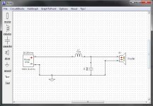
As an example: lets take a look at one simple circuit, a bog standard low pass filter for a woofer.
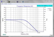
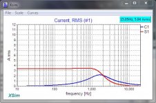
The first image shows you the XSim schematic. Note that in the second image the frequency response is as expected, the output rolls off with increasing frequency. The third panel shows the currents through the woofer (red) and the capacitor (blue)... both as expected.
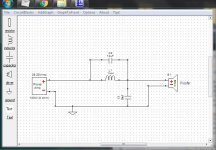
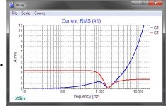
Now lets add what is often mistaken for a baffle step capacitor. The fourth image shows you the schematic. The last image shows you the current through the woofer (red) and the shunt capacitor (blue) ... Wait a minute, how did that happen?
Well, the answer is that when you added C2 you created an accidental path to ground through C1, which is drawing some pretty significant current from the amplifier... potentitally enough to damage it.
The missing element in avoiding mistakes like this is the knowledge of how these parts operate ... Capacitors pass more and more current as frequency increases. Thus C2 is able to bypass L1 creating a new path to ground through C1.
Again let me stress that I'm not trying scare anyone off. This is FUN stuff and it can be very rewarding (Just ask Andrew Jones)... but you really do need to know what you are doing if you don't want to run into disappointment after disappointment.
I'm very sure there are lots of people here with better crossover knowledge than me... and I look forward to learning from them.
Attachments
I agree, but I think it's beyond some here to see reactive components for their impedance, let alone their V, I and Z and whole circuit at once.
I wouldn't say it's beyond their capabilities... It's more like it's beyond their experience.
Consider the change in the definition of "electronics" in the last few years. It used to be that when someone mentioned electronics, people would visualize the inside of a radio or television set, they knew that we were referring to components. But of late with the growth of disposable technology that is mostly made with parts the size of fly poop, a lot of the younger set will envision a smartphone or a flat screen TV... the device has become the image, the parts inside are totally outside their experience so they don't even think about them.
This, I think, is a bad change in the hobby and the industry. People now view being a clever operator as "tech savvy" where we envisioned fixing things.
Douglas, it is a trap that many (including myself when I first started out) fall into (luckily for me I realised before I actually built something with the potential to kill my amp).
A big cap shunting the coil can seem to fix all sorts of problems in the frequency domain until you realize what it is doing to the impedance at particular frequencies. Definitely some fundamental understanding of what the elements in the circuit are doing not only helps avoid making disastrous mistakes, but also means you are better able to start at a sensible point rather than just chucking stuff in to see what effect it has.
Even if I think I know what I am doing, I always check the resulting impedance graph in the sims to make sure I've not done anything stupid.
One dumb thing I did on my MTM crossover, which wasn't pointed out to me for quite some time, was I put the LPAD *before* the crossover. My logic was that I didn't have to worry about changes to the crossover if I tuned the lpad. Despite knowing ohms law It didn't even occur to me that putting it before the crossover components was effectively lowering the impedance of an already low parallel pair of woofers more than they needed to be (since if it was after the caps in the tweeter network it would never appear as a resistance to be in parallel with the woofers).
I still haven't actually fixed that 🙄 I was planning to make a new crossover with the help of vituixcad and 180deg horizontal measurements, but that (along with a lot of other diy stuff) had to take a back seat to other things.
Tony.
Last edited:
Douglas, it is a trap that many (including myself when I first started out) fall into (luckily for me I realised before I actually built something with the potential to kill my amp).
A big cap shunting the coil can seem to fix all sorts of problems in the frequency domain until you realize what it is doing to the impedance at particular frequencies. Definitely some fundamental understanding of what the elements in the circuit are doing not only helps avoid making disastrous mistakes, but also means you are better able to start at a sensible point rather than just chucking stuff in to see what effect it has.
There are all sorts of pitfalls... your l-pad example is a good one as well. The problem of doing this with limited background is that you tend to look at the effects without considering or knowing the side-effects or failure modes. It's not an uncommon mistake, engineers do it too, and then we humble service techs get to fix it... hundreds of times.
It is actually quite surprising how different things look when you have to fix the problems you've caused. 😱
Even if I think I know what I am doing, I always check the resulting impedance graph in the sims to make sure I've not done anything stupid.
In XSim you can go to "Add Graph" then "More" and open a "Component Current" panel to monitor the actual load being imposed by various parts. I find it to be far more informative than the impedance charts. The error of adding C2 in my example likely would not have been caught otherwise.
I was planning to make a new crossover with the help of vituixcad and 180deg horizontal measurements, but that (along with a lot of other diy stuff) had to take a back seat to other things.
That happens rather a lot, doesn't it?
I wish I had a dollar for every time something I want to do had to wait for something that actually needed doing.
Last edited:
Hehe. I've just pasted in the text of the next installment (which I last updated in Feb this year 😱 ) https://www.diyaudio.com/forums/multi-way/332688-design-own-speaker-scratch.html#post5668314
I think my next step was going to be to do a simulation of this theoretical combo of drivers and baffle. I would ideally like to actualy buy these drivers and make what is simmed and then do proper measurements to see how close or far from the prediction it really turned out. That would also help with the planned measurements posts.
Anyway apologies to everyone who's been waiting for this thread to progress, life kinda got in the way!
The comment at the end of the post about the box alignment was around how to (potentially) adjust the manufacturers traced curve to be more like the response in your chosen alignment. This is a post I made on it before https://www.diyaudio.com/forums/multi-way/325406-project-revised.html#post5505274 Actually I may link to that from the main post...
Tony.
Hello, new to the forum and I am about to build my first speaker.
I´ve been playing around a bit with VituixCAD and have "settled" on a crossover design for my 2-way RS180P-8/ND25FA-4 build.
As I have learned after I ordered some nicer grade capacitors and inductors, it might not be that simple.
So my question is, should I return these parts, and instead buy a number of "low grade" capacitors and inductors in order to try out what μF number and mH gives the best FS, and then just buy the more expencive stuff based on those?
Or will there make no sense to test the speaker using electrolyte capacitor and smaller gauge wire inductors even though they have the same numbers on them or measured?
BR N
Somewhat tough question. If your measurements and simulation are good then you may be happy with what you have purchased, but no gaurantees. Electrolytics are ok for prototyping (with the exception in my experience of notch filters where they do not work well at all).
What I did was buy a range of cheaper polyprop film caps (Axon from parts connexion) and some cheap coils from the local electronics shop. I bought a bunch of 1uf film caps so I could add in 1uf increments to cap values for "tuning" purposes.
Once you get good correlations between what you have simulated and what you measure with the final implementation then you can be much more confident in ordering based on your sims.
Tony.
I don't mind using a good electrolytic capacitor on a tweeter, and a slightly higher resistance inductor shouldn't stand in the way of a good design. The component values are important to find out.
Okay thanks, I have only done some VituixCAD simulation using parameters from Dayton Audio, and bought 100USD worth of XO parts based on that... Fortunately I can still return it and get some cheaper stuff to start with. It´s a DIY audio store so their electrolytic capacitors should be "audio grade".
I was just worried that I will perfect the frequency response, and to then see it completely change as I upgrade the XO components.
I was just worried that I will perfect the frequency response, and to then see it completely change as I upgrade the XO components.
Cap tolerance is one area where you may run into issues (electrolytics generally having wide tolerance ranges). You probably need to measure the actual value of the caps used in the prototype and then try and get high precision caps (or buy from someone with a matching service) to ensure what you upgrade to actually matches the values of the prototype.
One other area where you may run into problems prototying with electro's is you may get some peaking when you change to film caps (the sims should show peaking if you have no ESR in the caps). Electrolytics have higher esr which will tend to damp resonances which can occur due to interactions between the caps and coils (not an issue for 1st order electrical crossovers)
Also make sure that the electrolytics are specifically for crossover duty. They need to be non-polar and the voltage needs to be high enough to be suitable for crossover use. If you are only going to test with a low wattage amp, then 50V should probably be ok, but 100V would be preferable.
Tony.
You can get peaking greater than the original response after adding a single component.not an issue for 1st order electrical crossovers
Wayne Parham devotes a chapter to peaking and 1st order networks in his nice
Pi Speaker Crossover Document - analysis of circuits used in waveguide and constant directivity loudspeakers
Pi Speaker Crossover Document - analysis of circuits used in waveguide and constant directivity loudspeakers
Good catch AllenB, yes I should know, as I've seen it, sometimes we forget what we have learned 🙂
Tony.
Tony.
- Home
- Loudspeakers
- Multi-Way
- Design your own speaker from scratch discussion thread