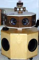
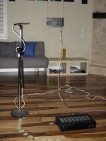
Another approach is to use closed boxes with drivers on both the front and back. By using relays or multiple amps, the phase of the speakers on the back of the baffle can be reversed. That's what I did about 10 years ago for the speakers in the picture. There is a relay board inside that reverses the polarity of the speakers on the back, so you can used them as dipoles or monopoles. I never finished off all of the software that it takes to control these things, so they got stored in a closet. But it's time to finish them off...I need to do something with them.
I've got a prototype for a 20-channel line array amp with DSP on each channel, and I am updating that design to use the ADI SSM3582 amps for each channel. I can adapt this design for this speaker, at least, that is one of the plans I have for these speakers. The amp will be controlled as an IoT device using MQTT, and I have an Android app that can be adapted to provide a convenient GUI for the switching and frequency compensation for monopole vs. dipole. This speaker could also be configured as a 3-way, 4-way or 5-way system, but the software to provide that flexibility won't be easy, and it may get deferred.
I don't have a schedule for getting this done so I don't know when it will happen, but the pieces are either here or getting worked.
Attachments
It's just like the title says, 20-20k (the audio band) with dipole radiation. Now by "dipole" I do not mean "open baffle". Most if not all open baffle systems are not really dipolar, especially above about 2kHz unless the highest band is handled by a dipolar ribbon, etc. This is because the radiation pattern to the rear is often much different from the front, and likely with some messy and problematic response behavior. Since most people do not even think about what is going out the rear, this tends to slip under the radar. But if you want to really make a "dipole" then you must pay attention to the rear output and it should be as much like the front output as possible because you "hear" the sound radiated into all axes.Good evening Charlie....
Trying to get a grip on what your goal really is....
I've previously seen you make these sweeping claims that this is all just a simple design issue, etc. I don't agree. This might be the case for bass up to a few hundred Hertz but once you get to 1kHz and above things get tricky when you are trying to make a true dipole. Try measuring your system to the rear and see what you find... Now I am not necessarily arguing here that a true 20-20k dipole is superior, however, my last prototype did sound very good and that was the case pretty much anywhere in the room (room had lots of reflecting/hard surfaces) because the radiation had the same tonal balance in pretty much every direction. A dipole type loudspeaker can be designed to do that, and this is the primary reason why I am endeavoring to build such a speaker.20-20K open baffle is a simple design exercise... as with the Iron Law, the compromise between how big, how efficient and how loud do you need to play. It is a 20 minute design issue. The real variable is how much money you can justify spending!
Another approach is to use closed boxes with drivers on both the front and back. By using relays or multiple amps, the phase of the speakers on the back of the baffle can be reversed.
Hi Neil,
Yes, I have done that, and have also experimented with a back-to-back dual-monopole-plus-filter woofer system that has a varying pattern, changing from monopole in the low bass (below 80Hz), thru cardioid, to dipole at about 250Hz.
I could implement a dipole pattern, use the varying pattern system, or just implement monopole subwoofers and within the crossover region between monpole subs and dipole mid I will get a cardioid for free as a result of the way that monopole and dipole radiation sums.
So, lots of options! I think it might make for some fun comparisons once I get it all set up.
Last edited:
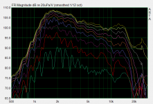
I thought I would show the responses I measured previously with the driver hanging by wires and away from boundaries, for the drivers that I plan to use in my 3-way dipole system (e.g. a stereo SWT arrangement, with S=Subwoofer, W=Woofer and T=Tweeter). Using only a 3-way with nude drivers requires some wide bandwidth and careful selection of driver size, but I think I have a set of drivers that will work well in this application.
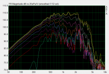
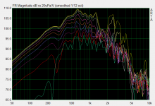
Attached are multi-axis measurements in the horizontal plane. For the "W" driver there are two plots - these are data that was taken separately at the front and rear sides of the driver. As you can see, very similar responses. The main difference is in the rear response, where there is a dip in the output around 1.3-2kHz in the near-on-axis responses. Note that all SPL levels are only relative, not absolute.
I also demoed and measured a 4-way SWMT design last year (since disassembled) that uses a 6" midwoofer to span about 750Hz- 2.5kHz, but I have decided try the 3-way system first. It would be an easy matter to add the midwoofer, however, it takes up some vertical space and I could not easily accommodate the subs below because the tweeter would be located too high. Instead of stereo subs I would use a separate, large H-frame that I have built around a high-Xmax 18" pro driver as a central mono sub, with the remaining 3-way stereo pair flanking it.
The "T" driver measurement is for a back-to-back dome tweeter setup that I came up with and which I am still developing.
I hope to cross over from M to T just under 2kHz with a steep slope using IIR DSP filtering. This is mainly determined by the distortion profile of the tweeter, and I would go even lower if I could. I may try to do some group delay EQ using FIR filtering later, to see if flattening the group delay (there will be a peak around the crossover point) will result in any audible effect.
For now I am moving ahead with the 3-way system (without midwoofer). I have finally started to build the new frame by which I am hanging the drivers and installing the drivers into it. The frame straddles and sits above the subwoofers so that vibration between drivers is completely decoupled. This is also real a benefit of using the "fly by wire" mounting.
Attachments
Last edited:
Now here is something really really interesting.Another approach is to use closed boxes with drivers on both the front and back. By using relays or multiple amps, the phase of the speakers on the back of the baffle can be reversed. That's what I did about 10 years ago for the speakers in the picture. There is a relay board inside that reverses the polarity of the speakers on the back, so you can used them as dipoles or monopoles.
First, as per my post #299, a front and back sub box sounds like a very good solution to having dipole ambience without sacrificing good bass. But still with a some (or all) of the phase cancellation problem unabated.
But of really significant conceptual importance, the box provides the ideal test of phase cancellation in practice. I've long argued that the textbook diagram of dipole sound of the rear sound sneaking around and annihilating the front sound is silly. The rear sound bounces around and the phases get messed up a lot. So the annihilation is nothing like the textbook diagram.
Neil's box can provide a meaningful test. Comparisons can be run among four conditions: front driver only, rear driver only, front and rear driven in phase, and front and rear driven in reverse polarity.
Nothing could be simpler to set up and run with REW, needing just a single mic location and obviously even the laptop mic would be just fine for this type of comparison.
B.
Last edited:
The front-back cancellation is clearly audible with my system. Standing between the loudspeakers facing the side of one there's no sound emanating from the loudspeaker, you only hear the reflections from the side(front and back wall), it's a strange sensation. The Linkwitz Orion did not behave like this, you could always hear sound emanating from the loudspeaker.
I've long argued that the textbook diagram of dipole sound of the rear sound sneaking around and annihilating the front sound is silly. The rear sound bounces around and the phases get messed up a lot. So the annihilation is nothing like the textbook diagram.
Um, I hate to break it to you, but at low frequencies the "textbook" diagram is pretty darn accurate. Each driver in a closed box is just like a monopole source at low frequencies. Sound radiates out and propagates into space in all directions. It's well known that long wavelengths simply bend around objects that are smaller than about half the wavelength and continue unaffected. At 100Hz the wavelength is already about 11 ft (3.5m) long, so most domestic objects within the room do not have much influence over the propagating wavefront.
Because a low frequency audio source like a subwoofer behaves just like a monopole you can model one as such with pretty good accuracy. There is no "getting messed up". But as a wave propagates it does undergo attenuation (its an expanding wave) and has a constantly changing phase. To accurately calculate what happens with two monopole sources that make up a dipole at low frequencies you simply do a vector addition of the two propagating waves from their origin to whatever point in space you would like to know the resulting free-field sum.
Lastly, I'm not MODELING the higher frequency dipole responses of my drivers suspended in free air, I'm measuring them. The proof is right there in the shape and features of the response, and I do not see how you can conclude anything else. Did I perhaps misunderstand you or something?
Well, but what about all that "bouncing around"? Well, now you are talking about something different: the influence of the room. This is a completely different issue to tackle and has nothing to do with the source - it's two decoupled problems, really. So "bouncing around" has nothing to do with how a dipole source radiates sound and the roof effect is not the subject of this thread. Likewise, you will get about the same amount of "bouncing around" whether you have a monopole or dipole source.
What I am really chasing after with this thread and project is the the creation a dipole source with wide bandwidth, as wide as the audio spectrum. But since the question/concern about dipole vs monopole bass always comes up, I have come up with a way to make the system capable of being outfitted with both types. This should make for some interesting listening tests.
The front-back cancellation is clearly audible with my system. Standing between the loudspeakers facing the side of one there's no sound emanating from the loudspeaker, you only hear the reflections from the side(front and back wall), it's a strange sensation. The Linkwitz Orion did not behave like this, you could always hear sound emanating from the loudspeaker.
YES! I find that really cool, actually. In one of my prototypes I rotated the speakers outwards so that the 90deg null pointed at the listening position so that I was only hearing the reverberant field. Wow.
I find that with a real dipole type loudspeaker I can walk around to the side and in between the speaker and hear a very consistent sound.
Neil's box can provide a meaningful test. Comparisons can be run among four conditions: front driver only, rear driver only, front and rear driven in phase, and front and rear driven in reverse polarity.
These speakers were supposed to be a test fixture for both dipole/monopole and various crossover types and configurations -- 3-way to 5-way, with a flexible mix of crossover slopes and frequencies. The amps were re-purposed Spherex 6-channel amps that use the Apogee DDX8229 (STA308a) chip for DSP. Those chips provide over 10 biquads per channel, which was enough to implement all of the crossover types I needed.
However, the STA308a chip only uses 24-bit coefficients, which is fine for higher frequencies but is not adequate for filters below 200Hz or so. Below 200Hz, most of the "digits" for the filters are just placeholders rather than significant digits, so you start to introduce noise. I could never bring myself to finish this project, because it was going to be a considerable effort to implement the software and I had hesitations about the quality of the low frequency filters.
So my plan now is to update my line array amp and adapt it to this speaker. The new version of the line array amp will use the ADAU1452 as the DSP, rather than 3 ADAU1701 chips. There is still a lot of HW design and software that will be needed, but it won't be a high risk effort, since I have a lot of existing pieces that I know will work.
If I can get this doing what I want it to, I'll probably loan it out for evaluations. Could be very interesting at DIY gatherings.
Well, but what about all that "bouncing around"? Well, now you are talking about something different: the influence of the room. This is a completely different issue to tackle and has nothing to do with the source - it's two decoupled problems, really. So "bouncing around" has nothing to do with how a dipole source radiates sound and the roof effect is not the subject of this thread. Likewise, you will get about the same amount of "bouncing around" whether you have a monopole or dipole source.
Pardon me, I didn't realize this thread was only about listening to music in anechoic chambers.
B.
Last edited:
I could never bring myself to finish this project, because...
Sounds like some of my old projects.
But for the simple four test runs, just a matter of connecting ordinary base-band audio signals to the woofers. Since nothing but freq response matters, almost any amp can be used.
B.
Pardon me, I didn't realize this thread was only about listening to music in anechoic chambers.
B.
No, sorry, that was not my intended point.
I consider the design of the loudspeaker, and the consideration of how a particular room will influence the sound from the loudspeaker, to be to completely separate problems. As a result, I design a loudspeaker and measure it under quasi-free-field (2pi space) conditions. One is always able to add EQ or room correction later, and no two rooms are alike.
YES! I find that really cool, actually. In one of my prototypes I rotated the speakers outwards so that the 90deg null pointed at the listening position so that I was only hearing the reverberant field. Wow.
I find that with a real dipole type loudspeaker I can walk around to the side and in between the speaker and hear a very consistent sound.
Indeed, same here. The timbre does not change when I walk around the loudspeakers, or the room for that matter. A direct result of the constant directivity of a real dipole as opposed to a generic open baffle system.
I see 9 curves in each of your 3 measurement pics. Are these at 10 degree intervals from on-axis to 90 degrees?I thought I would show the responses I measured previously with the driver hanging by wires and away from boundaries, for the drivers that I plan to use in my 3-way dipole system (e.g. a stereo SWT arrangement, with S=Subwoofer, W=Woofer and T=Tweeter).
Are these measured in a room? If so, could you post a diagram of the room dimensions (including height) and exactly where the dipole & mike were place? Did you rotate the speaker?
What software are you using?
Just to introduce some data into the discussion, see:
https://www.diyaudio.com/forums/subwoofers/339121-subs-reversed-polarity-surprise.html#post5822396
Naive to think EQ fixes rooms, maybe a bit... at least until you move your measurement mic a few inches and find you got it all wrong. Likewise for the reductionist model: why not start by studying dipoles in vacuums. Then add air, then add rooms, then add the preferences of the listener. As the link above shows, real gap between understanding a dipole in the abstract and making a speaker that sounds good in your room, Linkwitz Transform or not.
B.
I see 9 curves in each of your 3 measurement pics. Are these at 10 degree intervals from on-axis to 90 degrees?
Are these measured in a room? If so, could you post a diagram of the room dimensions (including height) and exactly where the dipole & mike were place? Did you rotate the speaker?
What software are you using?
This was a large, 2 story high room in my previous home. So it might be 30x30 and 20 feet high. I was able to get about 50Hz resolution on my measurements. It helps that dipoles do not radiate much energy down towards the floor, so the floor reflection is minimal.
I set up the drivers between a couple of PA speaker posts, between which I ran a piece of wood. The drivers were hung by wires from the piece of wood. Then I marked out angles on the floor using tape. I use a rudimentary system where I can easily mark out 0-45-90 and then I fill in between those at 22, 66 and then in between those at 11, 33, 57, etc. I don't find a need to be any more precise.
If you hover over each image you should be able to see the filename in the browser at bottom and that is descriptive regarding angle and so on.
Attachments
[B said:Gerrit Boers[/B]] The front-back cancellation is clearly audible with my system. Standing between the loudspeakers facing the side of one there's no sound emanating from the loudspeaker, you only hear the reflections from the side(front and back wall), it's a strange sensation.
In post #250 I show a pic of the Listening Area for good stereo with Option 1.I find that with a real dipole type loudspeaker I can walk around to the side and in between the speaker and hear a very consistent sound.
But in fact, the Listening Area actually covers more than the back 2/3 of the whole room .. including the areas OUTSIDE the 2 dashed lines which are the Nulls of the 2 dipoles.
Outside the 2 lines, you have a clear impression of a large door to a performing space defined by the speakers with a performance happening inside. When you move across the line, the impression isn't that you have moved in front of the door. Instead the aural impression is as though you have moved through the door INTO the performing space.
There's more of what you will HEAR in the Option 1 User Manual. As I said, there is only slight Marketing BS. The descriptions of what you HEAR are pukka.
Well, let's see what you are up to Ben. Here's your report "with data" from the thread you started today:
You little experiment has absolutely nothing to do with a dipole or dipole source. According to what you wrote, you just tossed some subs into the corners of the room:
When you have something that resembles a dipole source set up, and can figure out how to make some proper measurements, let us know.
It is an Article of Faith that polarities must be preserved. And for dipoles, that the phase annihilation diagram for woofer frequencies in the textbook is an Eternal Truth.
On the other side, anybody with experience fooling with phase and even with polarity and certainly with dipoles, knows that the sound hits walls and is in a multiple of ways shaken from its phase locksteps.
So I figured there's a real simple way for a person with a Behringer DCX2496 - the all-singing all-dancing DSP - to explore the notion with about 6 button presses of the DSP box.
The subs are in the front corners of the room. L is a 5-cu ft sealed box and the R a 17-foot labyrinth. Both with some EQ. A mic was placed mid-way between the subs and near my listening chair. The REW sweep is 10-500 Hz (OK, 10 Hz is pushing it a bit with my 1980 JVC receiver amp, but you can see for yourself what the mic picks up).
The first illustration shows the (1) L and (2) R traces when run separately. Many similarities are reflections of the room (literally, of course).
The second illustration shows the (1) R sub trace and the (2) R sub with polarity inverted trace. Many readers will notice a certain overlap.
The third illustration shows results when (1) both subs are running and when the (2) R sub is inverted. Needless to say, the reversed trace is the lower one. But not annihilated. Far from it.
The fourth illustration repeats the inverted trace shown in the third illustration. Funny, it looks so much better than the non-inverted trace. Maybe I'll raise the volume control and keep that. I bet just the thought of somebody doing such a thing would cause indigestion among many members here.
B.
You little experiment has absolutely nothing to do with a dipole or dipole source. According to what you wrote, you just tossed some subs into the corners of the room:
and you reversed the phase of one of them. Then you did "in room" measurements. Is it any surprise you are measuring the room response here, and nothing much about the sources themselves? Did you even bother to do any gating? What made you think that two subs in the corners with one having reversed phase is anything like what I am doing with dipoles???The subs are in the front corners of the room
When you have something that resembles a dipole source set up, and can figure out how to make some proper measurements, let us know.
In post #250 I show a pic of the Listening Area for good stereo with Option 1.
But in fact, the Listening Area actually covers more than the back 2/3 of the whole room .. including the areas OUTSIDE the 2 dashed lines which are the Nulls of the 2 dipoles.
Outside the 2 lines, you have a clear impression of a large door to a performing space defined by the speakers with a performance happening inside. When you move across the line, the impression isn't that you have moved in front of the door. Instead the aural impression is as though you have moved through the door INTO the performing space.
There's more of what you will HEAR in the Option 1 User Manual. As I said, there is only slight Marketing BS. The descriptions of what you HEAR are pukka.
Although that is an interesting (but definitely plausible) way to set up a dipole loudspeaker, that is not how I generally do it. Instead I position the speakers in the usual way, with drivers facing the listener and away from the rear wall by at least 1-1.5m and away from the side walls by 2m if possible, but at least by 1m from each wall. I do not like to toe the speaker inwards.
- Home
- Loudspeakers
- Multi-Way
- In Pursuit of a 20-20k Dipole Loudspeaker