Thanks for this Charlie. What was the measuring distance? This is important when measuring dipoles.This was a large, 2 story high room in my previous home. So it might be 30x30 and 20 feet high. I was able to get about 50Hz resolution on my measurements.
Are you using ARTA's Dual Gated Frequency Response? In a 20' high room, you will only be able to get 'anechoic' response down to about 100Hz (with 1m measuring distance). That's with Gate1 set just before the 1st reflection.
I'm not sure exactly what ARTA is doing with Dual Gated Frequency Response. It might be similar to my bastardized version of Benjamin's method which is a 'best guess' of what is happening below the 'frequency' of the first reflection.
But actually, I think your measurements are quite good and it is a shame you no longer have access to this big space. 🙂
-----------------------
You should consider using a baffle of some sort .. especially at LF. Departures from 'true dipole' on a large baffle only appear when the wavelength approaches the baffle size .. eg 10' for 100Hz. You get worthwhile gains in sensitivity and Xmax requirements while still having 'pure' dipole directivity ... even more if you are prepared to have your dipole at the floor/side wall boundary 😎
The way to get around this is to have back-to-back drivers out of phase. With properly matched units, this will have MUCH more consistent front/back directivity.Attached are multi-axis measurements in the horizontal plane. For the "W" driver there are two plots - these are data that was taken separately at the front and rear sides of the driver. As you can see, very similar responses. The main difference is in the rear response, where there is a dip in the output around 1.3-2kHz in the rear-on-axis responses.
Directivity will narrow somewhat but will still be smoothly symmetrical. To reduce the narrowing from pure dipole, you need to use smaller units so the back-to-back units can be closer together. Don't forget a large unit hanging in free air also starts departing from pure dipole .. in your case, much more than the back-to-back units.
Last edited:
A key issue in this thread is how to address cancellation, which of course, only relates to lower frequencies. I've argued that the classic textbook (or CharlieLaub) approach does the usual wave arithmetic.You little experiment has absolutely nothing to do with a dipole or dipole source. According to what you wrote, you just tossed some subs into the corners of the room:and you reversed the phase of one of them. Then you did "in room" measurements. Is it any surprise you are measuring the room response here, and nothing much about the sources themselves? Did you even bother to do any gating? What made you think that two subs in the corners with one having reversed phase is anything like what I am doing with dipoles???
When you have something that resembles a dipole source set up, and can figure out how to make some proper measurements, let us know.
The point of my measurements is that even in the worst of cases, even testing as low as 10 Hz, the textbook arithmetic doesn't hold all that well. It is the results of bouncing off the walls and the irregular distances and phase irregularities that have an impact on the bass in a dipole.
BTW, I started taking the backs off my Bozak speaker boxes in 1968 (when I worked at Bell Labs in Murray Hill, NJ) and have continued the practice since. At my age, I can barely compute the length of time that is.
BTW, ESL owners (ahem, ahem.... since 1977 about), have since time immemorial (at least by ESL standards) always kept their cells (which are always dipoles) a yard or so from the wall. Welcome to the club.
So, I guess I can claim a certain modest acquaintance with making great dipole sound.
B.
Last edited:
Please, lt's just wait a while for more measurements!
Dynamic drivers present challenges as dipole when frequency goes 2kHz> because of diameter and asymmetry of the construction. Nearfield measurements tell this,but don't telll where dipole cancellation starts to get disturbed.
Lowest octave is another challenge, both for excursion of the drivers and the walls/room making whoopies.
June-July is fine for outdoor activites...
I'm not sure, but do you mean two back to back out of phase drivers in free air or in closed boxes? In either case, I don't believe that you will get that to work. You will likely encounter problems at mid (500-1k Hz) to high (above 1k Hz) frequencies. In that band the distances of separation for two woofers grows too large and it's not possible to make it work properly like you can at low(er) frequencies.The way to get around this is to have back-to-back drivers out of phase. With properly matched units, this will have MUCH more consistent front/back directivity.
So far I think that what I am doing with back-to-back tweeters is pretty novel and successful in terms of forming a dipole. It's essentially two closed box sources, back to back, very close together. As far as I can recall, every other attempt by DIYers at using back-to-back domes to form a dipole tweeters has been unsuccessful. If you know of something that was successful please provide a link, etc.
Directivity will narrow somewhat but will still be smoothly symmetrical. To reduce the narrowing from pure dipole, you need to use smaller units so the back-to-back units can be closer together.
OK, I see you acknowledge the distance issue above. If you have some measurements of this back to back dipole working around 1kHz and above I would like to see them posted.
Directivity will narrow somewhat but will still be smoothly symmetrical. To reduce the narrowing from pure dipole, you need to use smaller units so the back-to-back units can be closer together. Don't forget a large unit hanging in free air also starts departing from pure dipole .. in your case, much more than the back-to-back units.
You mention "large units" and departure from dipole operation. I actually have observed that the opposite is true. You would think, based on a pure two-point-source model of a large driver (so D is relatively large), that the pattern would break down at some point. But what I observe, and what is shown in the measurements I presented in POST #304, is that the directivity pattern of a dipole holds for this driver (especially to the front) up to about the start of cone breakup at 2kHz. This is a 15" driver without baffle. How can it have that kind of response? I think the answer is that the driver's own "beaming" is causing the front and rear radiation to see less and less of each other. For a 15" this is starting to happen at 600Hz or so I think. Once you get close to 1kHz there is very little radiation to the sides and so you are simply getting to back-to-back directional sources (instead of monopole sources) that are out of phase with each other. This is still dipolar radiation, it's just not following the two-monopole model anymore.
SL used two 1" dome tweeters in his LX521 and I had the chance to talk to him about it, especially regarding the crossover point from the next driver, which was pretty high at 7kHz. He told me that he kept moving the crossover point up and doing measurements until he got the responses that he liked at 7kHz. By then the radiation from the two domes was beaming enough to no longer be interacting to the side and causing dipolar lobing (the separation distance around the LX521 baffle is getting too large stay below the dipole peak, so lobing results). It would seem that he came across the same phenomenon in his development.
When I look for driver candidates for dipole midrange (e.g. 200-2k Hz) I now look for larger drivers (e.g. 10" and up) with as small a voice coil as possible, good extended HF response, small magnet structure, and an open basket. Drivers like this, used "nude" (without a baffle), seem to have the most promise in the type of dipole loudspeaker systems that I am interested in building. The task is then to find a suitable dipolar tweeter that can operate from 2kHZ and up. If you add another band to cover the band below 200Hz you get a 3-way system.
This is a thread about dipole tweeters, also "back to back"
On the directivity of dipole tweeters
..."mission impossible"...
On the directivity of dipole tweeters
..."mission impossible"...
In Option 1, two back to back OOP 4.5" units maintain the dipole directivity up a xover of 5kHz. I'm sorry. This was nearly 40 yrs ago in my previous life.I'm not sure, but do you mean two back to back out of phase drivers in free air or in closed boxes? In either case, I don't believe that you will get that to work. You will likely encounter problems at mid (500-1k Hz) to high (above 1k Hz) frequencies. ... OK, I see you acknowledge the distance issue above. If you have some measurements of this back to back dipole working around 1kHz and above I would like to see them posted.
I think we need to be more precise.You mention "large units" and departure from dipole operation. I actually have observed that the opposite is true. You would think, based on a pure two-point-source model of a large driver (so D is relatively large), that the pattern would break down at some point. But what I observe, and what is shown in the measurements I presented in POST #304, is that the directivity pattern of a dipole holds for this driver (especially to the front) up to about the start of cone breakup at 2kHz. This is a 15" driver without baffle. .. This is still dipolar radiation, it's just not following the two-monopole model anymore.
...
When I look for driver candidates for dipole midrange (e.g. 200-2k Hz) I now look for larger drivers (e.g. 10" and up) with as small a voice coil as possible, good extended HF response, small magnet structure, and an open basket.
I thought when you said "dipole" you meant "speaker with accurate Fig-8 directivity". The usual textbook definition of "dipole" is 2 monopoles a short distance apart. But even this departs from Fig-8 as the wavelength approaches the 'short distance' .. what I think you call 'lobing'
Incidentally, I don't think the 'textbook' 2 monopole model simulates any practical unit/speaker usefully .. especially if you are investigating where the Fig-8 breaks down. It's OK for room simulations at LF only.
I was after "Fig-8 directivity over a large frequency range". Back-to-back out-of-phase units directivity starts narrowing but this IMHO is preferable to changing to 'unipolar' like you have between 1.3-2kHz. Also, closer examination of your curves show your 15" units are 'narrowing' a lot more by 700Hz than I like for my own 'dipole' implementations.
But all these effects are wavelength dependent. If your 15" unit goes 'unipolar' at 1.3kHz, to push this effect above 2.6kHz, you need to use a 7.5" unit. Probably wise to go a bit further if you are crossing over at 2kHz.
I'm also impressed by your twin treble directivity. Could you post a few pics of how you've done this?
Last edited:
I have no axe to grind. I'm just supplying one data point for what's required for your project. If your dipoles are not at the walls, you just need a larger baffle .. moot as you aren't using baffles 😎 (though a large 15" unit is its own baffle)Instead I position the speakers in the usual way, with drivers facing the listener and away from the rear wall by at least 1-1.5m and away from the side walls by 2m if possible, but at least by 1m from each wall. I do not like to toe the speaker inwards.
However you might like to take one practical suggestion from Option 1.
Instead of 1-1.5m from the rear wall, have exactly 1/3 of the room behind your dipoles. You will find bass is improved and also LF response consistency in the room. This works whether the dipoles are toed in or not, baffled or not. So for your old 30'x30' room, have your dipoles exactly 10' from the front wall.
Last edited:
Just a quick thought...
What if we took two identical drivers, mounted them facing forward and back on the same baffle, and then added some sound absorbing material to cover the magnet-side of each driver? I'm thinking an inch or two of recycled wool underlay.
I think this would produce useful results:
- The absorbing material will work best where irregularities will occur (ie, as the wavelengths become short and the magnet/basket structure becomes acoustically large.
- As you move down in frequency, the absorption becomes less effective, so you've transitioned to two drivers contributing, which will help counteract the acoustic rolloff of dipole systems.
It's very easy to prototype, and I happen to have some drivers I could try it with.
A mid/side stereo system is an interesting idea to me, so I'll give this a go the next time I get a day spare, and see how it goes.
Chris
Well, I finally had the time to get the speaker set up, a crossover developed, add a subwoofer (closed box) and do some listening and tweaking. All in mono, which is both more revealing than stereo and easier to build (only one speaker needed).
This particular prototype was in the guise of "can this work?" because it uses a 15" pro audio driver as midwoofer plus a back-to-back 1" dome tweeter as dipole. I would never in a million years suggest to anyone that they try to mate drivers of such disparate sizes, but I thought I would try it anyway. The measurements I had taken on each (FR+distoriton) showed that it just might work. If not, I have a plan B,C, and E waiting in the wings.
So, actually it's not bad! I created a crossover based on on-axis measurements only (although I did know what was going on off axis with each driver individually). The speaker is a nude open baffle, so the drivers are hung from a frame and their acoustic centers aligned physically. I checked this and it was only a couple of millimeters off on the first try, which was pure luck. Also, I knew that both to the front and rear the driver radiation should be the same, or almost exactly the same, for both drivers. I can listen on either side and the tonal balance of the speaker sounds the same. This also means that on other axes, the tonal balance should remain the same or similar. Off-axis listening supports this concept. I can also listen in the null (you hear primarily the room sound, it's not a perfect null but at least -20dB WRT the on-axis SPL) and the tonal balance there is also very similar to what I hear in front of the speaker. This is exactly what I have wanted to create with such a speaker build.
After some extended listening, there are (no surprises) some minor artifacts that creep in on some program material beause the tweeter is crossed too low and the woofer too high. But really they are not all that serious and about what I anticipated. I plan to keep tweaking the crossover to see if this can be improved.
The low end is being handled by two boxed 12" subs of modest design. I used a traditional crossover where each band has the same crossover point. I tried to overlap the subs and the woofer to create a region of cardioid from about 80-160Hz, but this was not anything to write home about so I reverted to crossing both over at 100Hz.
If I decide to keep experimenting with this prorotype I will replace the closed box subs with a pair of H-frame dipole subs that use an Eminence Alpha 15A in the mold of Martin King's investigations on OB, U-, and H-frames. For now I will do some more short listening sessions and continue to play with the crossover in my ACD design program after some feedback from the sessions.
Are you going to post some pics CharlieLaub?
I'm REALLY interested in your back-to-back dome trebles. As in any SOTA project, the devil is in the detail
I'm REALLY interested in your back-to-back dome trebles. As in any SOTA project, the devil is in the detail
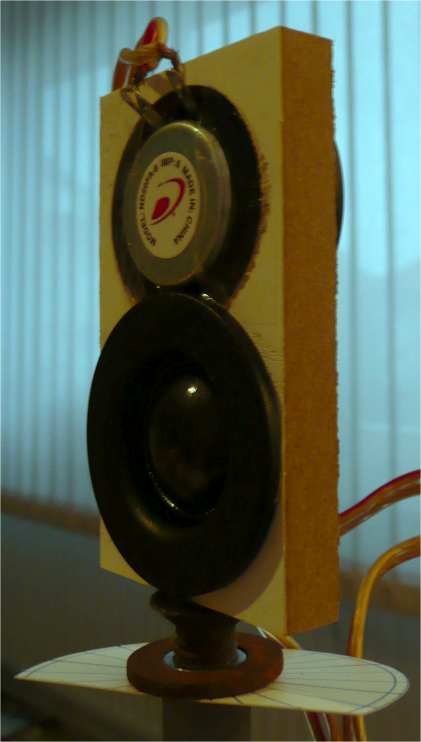
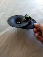
Sure, I am ready to post more info but I need to take some more pics. The dipole tweeter is constructed from a pair of small and inexpensive neo 1" dome waveguide loaded tweeters placed back-to-back. Because the magnet is so small I am able to position the tweeters with only a small offset and use the mounting holes on the waveguide/flange to hold them together with some machine screws. Originally I was just toying around with the idea but after I measured them the response was a very surprising and lovely dipole. I tried a couple of different ways to arrange them back to back, and the best pattern was obtained when I got the front-to-back distance as small as possible.
My guess about what is happening is this:
At "low" frequencies around 1kHz even with the waveguide the radiation is nearly monopole. So placing two back-to-back creates a dipole. At some frequency the pattern should break down because of the distance between the two domes and the size of the waveguide. Modeled as two monopoles, the response should become replete with nulls and other undesirables. But this doesn't happen, and that was quite surprising. Instead the dipole response pattern just continues all the way up until the top end around 18k or so. I think that the increased directivity from the waveguide causes the front and back radiation to no longer interact, and so you just get a front and rear lobe.
I have a new version of the back-to-back dipole in which I used a hole saw to remove a section of the edge of the waveguide that is the same diameter as the magnet assembly. This allows the two tweeters to next much closer. I was able to glue them together into a single unit, but I have not been able to make good multi-axis measurements on them yet. I will also put out some info on this in the near future.
That's all for now on the tweeters.
In other news, after some crossover tweaks the speaker (only one so far) is sounding pretty good. Let's see what the wife says... Time for a beer!
Last edited:
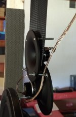
Here are some pics and details of my back-to-back dome dipole tweeter, and the prototype nude dipole system in which it is currently serving. I included one pic of the latest more compact version, but no measurements are available yet.
Note, to figure out what a particular photo is, hover over (but do not open) the thumbnail and look in the bottom browser bar for the filename, which should contain info about angles, whether the mic was in the front or back, etc.
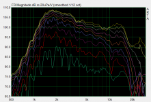
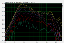
The tweeter is the Dayton ND25FW-4. It's an inexpensive (<$20 each) 1" neo dome in a plastic waveguide. I have attached measurements taken on the dipole pair in the horizontal plane, separately from the front and back, plus a distortion measurement. Distortion is low except for a bump in 2nd order around 1.5k. At higher levels things remain relatively similar, with the average level coming up a bit but staying below 1% until you go below 2kHz. Not bad for $20, eh? Keep in mind that the down-sloping response is flattened by bringing down the lower portion of the response to match the middle part, and the distortion should be quite low in actual use.
As I explained in the last post, I found that I could position these back to back relatively close together with the waveguides overlapped just by using long machine screws thru the mounting holes. When assembled this way, the distance in-between the waveguide mounting flanges is about 25mm, and the dome is recessed into the guide so the two acoustic centers are probably closely aligned in the front-to-back orientation. Not sure if this is critical or not, however, I initially had them spaced about 35mm apart and the dipole pattern was not as good.
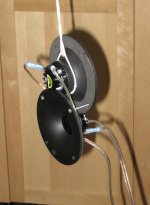
In order to bring the two waveguides even closer together, material that interferes must be removed. The tweeter itself it mounted into the back of the waveguide in a short cylindrical extrusion and this bumps against the rear surface of the waveguide of the mating tweeter unit. I used a hole saw of about the same diameter to carefully cut out the round interfering section of each waveguide. I was then able to mount the two waveguides with the cylindrical mounting extrusions sticking thru the other waveguide and butting up against each other. This brings the back-to-back separation of the waveguides down to about 16mm and also brings the up-and-down offset of the two domes down from about 62mm to about 42mm. Until I measure the responses I won't know whether the fact that there is now a partial cylinder sticking thru each waveguide will or will not create problems with the responses.
Please see the attached pic of this new and more compact arrangement.
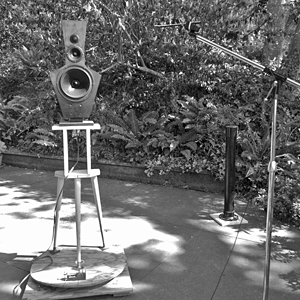
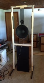
Also, I have attached a couple of pics showing the current prototype system, and how I mount the back-to-back dipole. Keep in mind that I just threw this together from some cheap 2x3 lumber... As I have mentioned elsewhere, it's difficult to freely hang the tweeters in free space and connect wires to them because they weigh very little. My solution is to use this plastic mesh - it's intended for embroidery work. The hole spacing is just about right for the mounting holes of the tweeter, and the mesh is semi-rigid, or enough so that it hangs without much twist, etc. It does not seem to affect the performance, at least from the measurements I have made on it, as mounted. The woofer should really be lower, e.g. just above the crossbar that is above the subwoofers, and the tweeters should hover just above the woofer. This means I can lower the top crossbar by about 10" (it's 6 feet tall now) and still accommodate everything, but the tweeter axis is a bit higher than usual. On the back side the tweeter is actually below the level of the woofer flange. Since its all acoustically aligned and there is lots of radiating surface from the large 15" woofer this doesn't seem to be a problem. It might even sound better from the rear than the front. It's a strange feeling to be looking at a woofer magnet but the sound is great... That shows that acoustically front = rear, which is a goal of this dipole system.
Note, to figure out what a particular photo is, hover over (but do not open) the thumbnail and look in the bottom browser bar for the filename, which should contain info about angles, whether the mic was in the front or back, etc.
The tweeter is the Dayton ND25FW-4. It's an inexpensive (<$20 each) 1" neo dome in a plastic waveguide. I have attached measurements taken on the dipole pair in the horizontal plane, separately from the front and back, plus a distortion measurement. Distortion is low except for a bump in 2nd order around 1.5k. At higher levels things remain relatively similar, with the average level coming up a bit but staying below 1% until you go below 2kHz. Not bad for $20, eh? Keep in mind that the down-sloping response is flattened by bringing down the lower portion of the response to match the middle part, and the distortion should be quite low in actual use.
As I explained in the last post, I found that I could position these back to back relatively close together with the waveguides overlapped just by using long machine screws thru the mounting holes. When assembled this way, the distance in-between the waveguide mounting flanges is about 25mm, and the dome is recessed into the guide so the two acoustic centers are probably closely aligned in the front-to-back orientation. Not sure if this is critical or not, however, I initially had them spaced about 35mm apart and the dipole pattern was not as good.
In order to bring the two waveguides even closer together, material that interferes must be removed. The tweeter itself it mounted into the back of the waveguide in a short cylindrical extrusion and this bumps against the rear surface of the waveguide of the mating tweeter unit. I used a hole saw of about the same diameter to carefully cut out the round interfering section of each waveguide. I was then able to mount the two waveguides with the cylindrical mounting extrusions sticking thru the other waveguide and butting up against each other. This brings the back-to-back separation of the waveguides down to about 16mm and also brings the up-and-down offset of the two domes down from about 62mm to about 42mm. Until I measure the responses I won't know whether the fact that there is now a partial cylinder sticking thru each waveguide will or will not create problems with the responses.
Please see the attached pic of this new and more compact arrangement.
Also, I have attached a couple of pics showing the current prototype system, and how I mount the back-to-back dipole. Keep in mind that I just threw this together from some cheap 2x3 lumber... As I have mentioned elsewhere, it's difficult to freely hang the tweeters in free space and connect wires to them because they weigh very little. My solution is to use this plastic mesh - it's intended for embroidery work. The hole spacing is just about right for the mounting holes of the tweeter, and the mesh is semi-rigid, or enough so that it hangs without much twist, etc. It does not seem to affect the performance, at least from the measurements I have made on it, as mounted. The woofer should really be lower, e.g. just above the crossbar that is above the subwoofers, and the tweeters should hover just above the woofer. This means I can lower the top crossbar by about 10" (it's 6 feet tall now) and still accommodate everything, but the tweeter axis is a bit higher than usual. On the back side the tweeter is actually below the level of the woofer flange. Since its all acoustically aligned and there is lots of radiating surface from the large 15" woofer this doesn't seem to be a problem. It might even sound better from the rear than the front. It's a strange feeling to be looking at a woofer magnet but the sound is great... That shows that acoustically front = rear, which is a goal of this dipole system.
Attachments
-
 ND25FW pair OFFSET back-to-back setup.JPG378.7 KB · Views: 425
 -
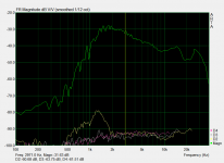 ND25FW-4 back-to-back OFFSET distortion.PNG45.2 KB · Views: 420
 -
 Dayton ND25FW-4 offset pair 25mm 0-11-22-33-44-55-67-78-90deg 70cm front.PNG42 KB · Views: 759
 -
 Dayton ND25FW-4 offset pair 25mm 0-11-22-33-44-55-67-78-90deg 70cm rear.PNG40.7 KB · Views: 667
 -
 IMG_20190629_122507498.jpg294.3 KB · Views: 413
 -
 IMG_20190629_122243189.jpg304.7 KB · Views: 314
 -
 IMG_20190629_122324327.jpg305.5 KB · Views: 305
Where are the measurements?
B.
I did 50Hz resolution measurements on the drivers previously, which I think I posted earlier. I also took some quick multi-axis measurements only in the front as mounted in the current "frame" to confirm that the frame does not impact the response off axis. Those seemed to look fine.
I used only on-axis measurement when developing the crossover. I also did an interference type measurement to check the acoustic center offset. At this point I have not done complete measurements of the "system". My primarily goal was to get the system up and running and do some listening to see if it could work.
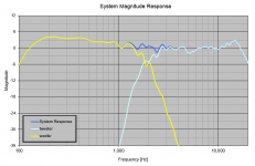
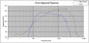
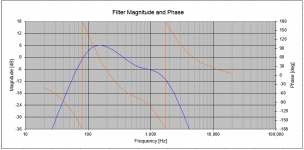
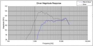
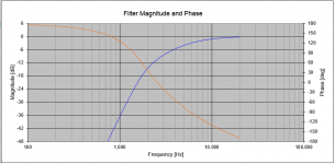
I have attached plots of the drivers (including as-measured and with the crossover filters active), the response of the filters, plus the system response for the current crossover from my ACD crossover development software.
Attachments
Thanks for measurements. Looks quite good.
Plots 2, 4, and 5 are centre-line, near-field, no EQ, with 1/6 smoothing????*
Nice if you could post the harmonic distortion plots too; tested at ordinary uncalibrated listening level is as meaningful to see as pushing for the peak loudness or bothering with calibration.
B.
* if I made the rules, I'd ask speaker forums to standardize on 1/12 for FRs unless other smoothing was more revealing.
Last edited:
The data in those plots was taken outdoors with the mic elevation putting the capsule about halfway between center of woofer and tweeter. The mic was about about 1.5-2m away from the drivers. The resolution was around 100Hz IIRC. I checked and found I used 1/12th octave smoothing. You can see this at the top of some of the earlier response plots (the text at the top).Plots 2, 4, and 5 are centre-line, near-field, no EQ, with 1/6 smoothing????
The dashed lines are the raw (as recorded) data, and the solid lines is the same driver but with its crossover filters active.
Nice to see the harmonic distortion plots too; ordinary uncalibrated listening level is as meaningful to see as pushing for the peak loudness.
B.
If I measure the system response again outdoors I will try to remember to record SPL and then take distortion measurements at a couple of different levels. You are correct - that would be useful info.
Last edited:
Thanks for efforts to explain. Yes, out of doors makes 1/12 look as smooth as 1/6 indoors.
Of course the rubber meets the road indoors (and twice as important for OBs that "use" the room twice as much); so great to see measurements - even near-field - done indoors.
I've been following a great argument that Toole started about FRs and room correction. In a nutshell, silly to say you can "correct" a room with EQ, bass aside. Leave it alone. Does your uncle sound different in different rooms (at least after 2 minutes of familiarization)?
B.
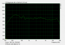
Thanks to Ben's gentle prodding I decided to just give it the good ol college try and see if I could take some indoor measurements. The system is set up in my basement in a long room and more or less in the middle of the room. The ceiling is only 7' tall, so I was not really expecting to be able to get any useful data because (I thought) I would need to shorten the gating window a lot. Well I was very surprised to see that I could get a resolution of 150Hz or so. Whaaaa? My guess is that the dipole null means the speaker is just not illuminating the ceiling, floor, or walls perpendicular to the speaker. We are left with reflections from far away walls only. I think. Anyway, the impulse did not show strong signs of a reflection up until where I gated it off so mark me down as pleasantly surprised.
With that preliminary check out of the way, I set up trying to calibrate the SPL level. I have a calibrated mic, but it passes through a pro audio DA/AD box that has gain for both the mic and the output level via knobs with no useful markings. Luckily I have an SPL meter, so I did an A-weighted reading at the mic, which I positioned at 1m exactly from the woofer frame in front of the speaker at about halfway in between the woofer and tweeter center axes. After much fiddling about I managed to figure out the levels, so what you see is the real 1m SPL. Man, 90dB@1m is rather louder than I realized!
So, attached I have attachments of the frequency response and distortion at 70dB, 80dB, and 90dB at 1m levels.
The system used:
Behringer ECM8000 calibrated by Spectrum Labs
Focusrite Scarlett Solo interface
computer doing DSP, signal routed in/out via ALC892 codec running at 96k/32bits
.
Attachments

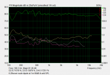
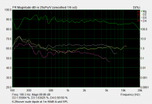
Nice HD%, clocking in around -40 dB (1%). Pretty good for cones (ESL can come in around -50 dB, ahem, ahem).
But you might already be bumping against the lower limits of your measuring system and the real figures are even lower.
But apropos the earlier dust-up about dipole rear waves sneaking around and annihilating the front wave - at least in textbook illustrations - how to evaluate?
First, there is your own modelling based on the size of the baffle and the arithmetic expectations given wave lengths.
Second might be altering the space behind an OB by moving further from wall or some serious absorbent back there, angling the panel, relation to side walls, etc. and seeing the consequences in the FR.
While nobody has a straw-man image that all the theoretical cancellation would occur, it would be interesting to see how much or how little is cancelled as you go down the freq scale into the relevant range.... and how much LT is needed.
B.
Last edited:
- Home
- Loudspeakers
- Multi-Way
- In Pursuit of a 20-20k Dipole Loudspeaker