 Mic posts moved to new thread
http://www.diyaudio.com/forums/equi...t-microphones-phase-response-calibration.html
Can someone please explain the concept and use of "time offset" field in the "measurements" tab?
Thanks in advance.
It does exactly the same thing as what the sample offset setting does in HOLM (but with a different unit): it moves the reference position (t=0) when considering the impulse response.
Placing it on the main/first/positive peak will result in a phase plot the reach 0° up high, making it close enough to the minimum-phase reponse (ignoring the low pass of the system...) to be easily corrected.
This temporal centering should normally be done in the measurement software prior to import (together with polarity), at least grossly, as it is basically the removal of the time delay.
The setting in rephase is intended for fine tuning only.
If you manipulate it in HOLM you will be able to see what that means for the phase response (similar to what you see in rephase) and impulse response together. That is one think is really like with HOLM: you can really "feel" the time/frequency relationship.
Last edited:
yes, simply enter the miniDSP EQs into an EQ bank with proportional Q type, use the "toggle constant Q / proportional Q" tool, and then report the constant Q values to the BSS.
Thanks! Really cool feature.
It does exactly the same thing as what the sample offset setting does in HOLM (but with a different unit): it moves the reference position (t=0) when considering the impulse response.
Placing it on the main/first/positive peak will result in a phase plot the reach 0° up high, making it close enough to the minimum-phase reponse (ignoring the low pass of the system...) to be easily corrected.
This temporal centering should normally be done in the measurement software prior to import (together with polarity), at least grossly, as it is basically the removal of the time delay.
The setting in rephase is intended for fine tuning only.
If you manipulate it in HOLM you will be able to see what that means for the phase response (similar to what you see in rephase) and impulse response together. That is one think is really like with HOLM: you can really "feel" the time/frequency relationship.
Thanks Pos.
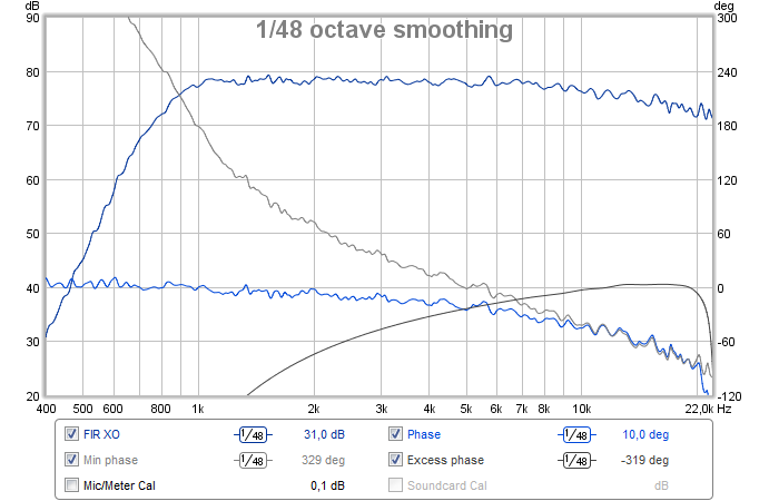
I designed and built a 3 way speaker and used Rephase to linearize its XO filters and got this nice result after some additional IIR eq on the HF:
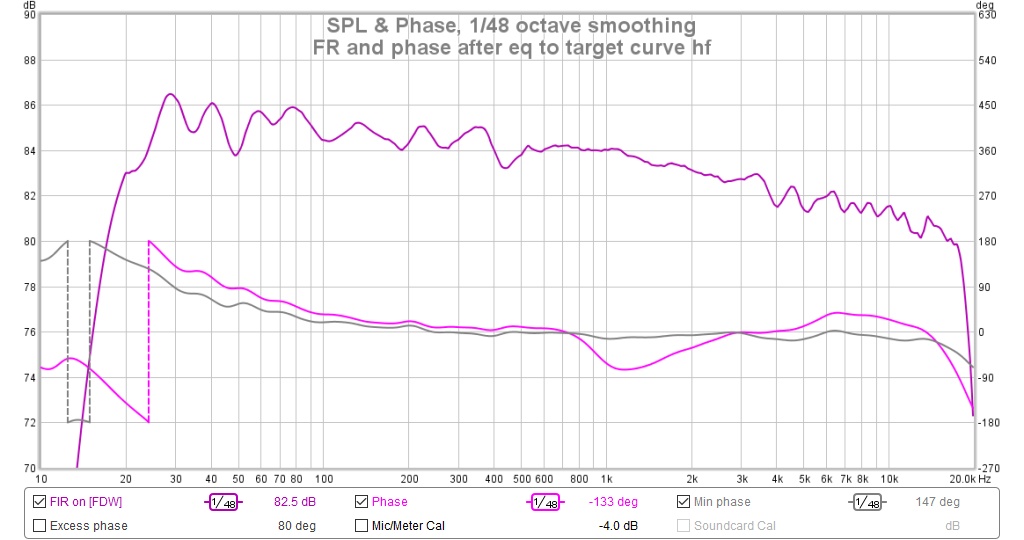
I wanted to bring it back into RePhase to flatten the phase around 1 Khz but the phase I see in Rephase is nothing like what I see in REW.
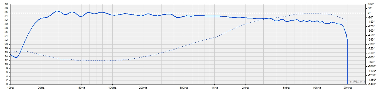
It looks like there is excess phase in the measurement that I don't see in REW. In REW I had shifted the IR to zero but that only affected the generated min phase.
Based on earlier posts, I thought Rephase time offset field would help but it doesn't. Any suggestions?
I wanted to bring it back into RePhase to flatten the phase around 1 Khz but the phase I see in Rephase is nothing like what I see in REW.
It looks like there is excess phase in the measurement that I don't see in REW. In REW I had shifted the IR to zero but that only affected the generated min phase.
Based on earlier posts, I thought Rephase time offset field would help but it doesn't. Any suggestions?
Attachments
found my problem w help from Wesayso. I was seeing phase of a filter already loaded via settings which added to the measurement phaseI designed and built a 3 way speaker and used Rephase to linearize its XO filters and got this nice result after some additional IIR eq on the HF:
I wanted to bring it back into RePhase to flatten the phase around 1 Khz but the phase I see in Rephase is nothing like what I see in REW.
It looks like there is excess phase in the measurement that I don't see in REW. In REW I had shifted the IR to zero but that only affected the generated min phase.
Based on earlier posts, I thought Rephase time offset field would help but it doesn't. Any suggestions?
Can anybody explain to me what exactly (mathematically) are referred to as minimum phase and excess phase?
I know that the Fourier transform phase response can be defined on terms of phase delay and group delay (or better, those parameters can be derived from the phase response), but mathematically I have heard about minimum phase only in relation to IIR filters, and I don't remember studying anything about excess phase. Is that the phase related to the time delay of the measurement, that can be zeroed by offsetting t0 in the phase graphic?
I know that the Fourier transform phase response can be defined on terms of phase delay and group delay (or better, those parameters can be derived from the phase response), but mathematically I have heard about minimum phase only in relation to IIR filters, and I don't remember studying anything about excess phase. Is that the phase related to the time delay of the measurement, that can be zeroed by offsetting t0 in the phase graphic?
Last edited:
sax512,
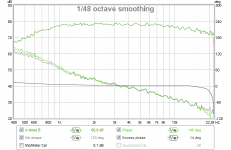
IIR filters are minimum phase, below curves in green show measured amplitude response and absolut phase, asking REW in grey curve to "Generate minimum phase" calculate how real minimum phase curve look for that particular amplitude response and the difference is excess phase. Black curve indicate difference and where it originates from is probably because soundcard/preamp/poweramp was not corrected for in REW settings but also if any reflections that have other distance than direct sum to amplitude or cancel amplitude it will be excess phase.

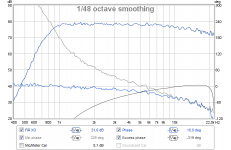
Now add a linear phase (FIR) XO point to above and hit "Generate minimum phase" will make excess phase error look huge compared to calculated IIR phase belonging to that particular amplitude response.
IIR filters are minimum phase, below curves in green show measured amplitude response and absolut phase, asking REW in grey curve to "Generate minimum phase" calculate how real minimum phase curve look for that particular amplitude response and the difference is excess phase. Black curve indicate difference and where it originates from is probably because soundcard/preamp/poweramp was not corrected for in REW settings but also if any reflections that have other distance than direct sum to amplitude or cancel amplitude it will be excess phase.
Now add a linear phase (FIR) XO point to above and hit "Generate minimum phase" will make excess phase error look huge compared to calculated IIR phase belonging to that particular amplitude response.
Attachments
Last edited:
Thank you, BRYTT
In other words, in the ideal case of no other external sources of phase shift such as chain devices and reflections, the minimum phase is the phase shift that you would measure if you had a perfect flat amplitude and linear phase graph and wanted to make the amplitude the same as the measured one with the use of IIRs.
While the excess phase is the difference (smoothed out, it seems) between that minuimum phase shift and the real measured one. In the case the phase had been linearized through the use of a FIR filter, the excess phase is the opposite of the minimum phase.
Did I get this right?
My 4-way loudspeaker has fir XO filters generated with rephase and executed through the convolution engine in Jriver.
I want to add a room EQ filter over this. Whats the best way to generate this filter and how do i add it to Jriver since its convolution engine is already being used for the XO/driver EQ filters.
I can integrate the room EQ into the individual driver EQ/XO filter. But i am wondering if i could keep them separate.
thanks
There is a good reason to keep them separate. The XO is a fixed funtion of your speaker while the Room EQ is subject to change everytime you move the speakers or just open a window. But you are free to combine both of course.Whats the best way to generate this filter and how do i add it to Jriver since its convolution engine is already being used for the XO/driver EQ filters.
I can integrate the room EQ into the individual driver EQ/XO filter. But i am wondering if i could keep them separate.
I dont kow if its "the best way" but this works:
- generate the room eq. I am using DRC-FIR but there are other software packages doing the same more or less.
- the filter you get is in form of a impulse response for each spaker. Now convolute this filter with the XO filter of your tweeter. The result is your new tweeter XO with inherited room EQ.
- repeat this for each way an for each speaker.
- one simple way to perform the convolution is to import the filters in REW as impulse responses and use the a*b function in the All SPL tab.
good luck
/ropf
My 4-way loudspeaker has fir XO filters generated with rephase and executed through the convolution engine in Jriver.
I want to add a room EQ filter over this. Whats the best way to generate this filter and how do i add it to Jriver since its convolution engine is already being used for the XO/driver EQ filters.
I can integrate the room EQ into the individual driver EQ/XO filter. But i am wondering if i could keep them separate.
thanks
In Foobar you can add more then one convolver.
Thanks ropf.
Thank ustas, but i think i will stick with Jriver for now.
In JRiver also, two convolvers plugins may work, it does with SIR_1 (http://www.siraudiotools.com/sir1.php )
+ convolverVST.
Biquads generated by the miniDSP Linkwitz-transform spreadsheet........
https://www.minidsp.com/applications/advanced-tools/linkwitz-transform
is there an easy way in rePhase to make an equivalent linear phase version of them...?
Right now, I turn on the biquad on the openDRC for magnitude correction, then need to go back to rePhase for phase correction of the biquad. Is there a way to do it all just once in rePhase?
thx, mark
- Home
- Design & Build
- Software Tools
- rePhase, a loudspeaker phase linearization, EQ and FIR filtering tool