The 4,5 ohms resistor sets the volume of the Vifa FR, it works as an attenuator. The 8 ohms together with the 2 mH inductor adjusts the top end, the 8 ohm adjusts the volume of the upper frequencies. Depending on your taste, room, music, speaker placement, blood pressure etc. you can tweak the two resistors in order to get a more refined sound. But you should start with the given values. Have fun!
Last edited by a moderator:
I an waanting to build the Manzanta but I am not willing to go passive cause I cannot afford the cost of the crossover. Has anyone used miniDSP or Hypex DSp for this project Please can someone guide what should be my crossoover in miniDSP. I have the 15" GRS and TC9 peerless
Active filtering has been mentioned several times in the thread. Here is a recent post.
https://www.diyaudio.com/community/threads/fast-fun-inexpensive-ob-project.110583/post-7033913
https://www.diyaudio.com/community/threads/fast-fun-inexpensive-ob-project.110583/post-7033913
Hi,
as I wrote somewhere I'm working on my own OB construction, going the hard but educative way, a thread will follow soon.
Why I'm writing here is the xo. I ended up crossing the woofer at about 100 Hz, above there is an FR, crossed much higher, and it sounds better and better. But - it shouldn't work, just like the Manzie shouldn't work. Woofer crossed at about 100 Hz, but the little Vifa can't possibly go down that far, and is crossed far above with 6 uF. So it shouldn't work, but it does. There should be a huge gap/trough between 100 Hz and 3-4 kHz. But there isn't. Is there an explanation?
Many thanks in advance!
I am afraid you are confusing filter placement with crossover point.
The crossover point is where two drivers are contributing equally to the sound level.
Lacking resonant peak filters and zobels, gentle filters rarely provide crossover points close to their theoretical -3 or -6db points.
The crossover point is where two drivers are contributing equally to the sound level.
Lacking resonant peak filters and zobels, gentle filters rarely provide crossover points close to their theoretical -3 or -6db points.
Yes, I know both ") Maybe I was unclear.
Maybe I was unclear.
The Manzie has a first order low pass filter for the woofer, with an 18 (or 20) mH inductor, which means the filter is set at about 70 Hz, so we get -6dB at about 140 Hz (please correct me if I´m wrong).
For the FR there is a first order high pass filter with 6 µF, which means it is set at about 3,4 kHz, we get -6 dB at about 1,7 kHz (again, please correct me ).
But what happens between 140 Hz and 1,7 kHz? The two drivers meet at about 200 Hz, this is about -8 dB, and there is a trough, in the simulation it would look like on the picture below (I hope I have the right frd-files for the Peerles woofer and the TC9). That´s what I don´t check
Or is it just the electrical crossing, and is the acoustical a different thing?
Or am I completely wrong?
Thanks for any explanation in advance.

Maybe I was unclear.The Manzie has a first order low pass filter for the woofer, with an 18 (or 20) mH inductor, which means the filter is set at about 70 Hz, so we get -6dB at about 140 Hz (please correct me if I´m wrong).
For the FR there is a first order high pass filter with 6 µF, which means it is set at about 3,4 kHz, we get -6 dB at about 1,7 kHz (again, please correct me
).But what happens between 140 Hz and 1,7 kHz? The two drivers meet at about 200 Hz, this is about -8 dB, and there is a trough, in the simulation it would look like on the picture below (I hope I have the right frd-files for the Peerles woofer and the TC9). That´s what I don´t check
Or is it just the electrical crossing, and is the acoustical a different thing?
Or am I completely wrong?
Thanks for any explanation in advance.
Last edited by a moderator:
I found it
Well, it's a combination of electrical and acoustical crossing, so the real crossing point of the woofer is at 750 Hz, despite of the 20 mH, I never would have thought. The baffle and the xo together gives a 2nd oder, that's why the FR is connected with reversed polarity. Everything is slowly starting to make sense
Well, it's a combination of electrical and acoustical crossing, so the real crossing point of the woofer is at 750 Hz, despite of the 20 mH, I never would have thought. The baffle and the xo together gives a 2nd oder, that's why the FR is connected with reversed polarity. Everything is slowly starting to make sense
Last edited by a moderator:
In this post there is an explanation of how the crossover works:
https://www.diyaudio.com/community/threads/fast-fun-inexpensive-ob-project.110583/post-4573958
Although no spelled out in detail it does mention how the very low electrical crossover point helps to flatten the woofer response. Remember, this woofer is not in a box, nor is it on an infinite baffle. The bass frequencies wrapping around the baffle to the back side cancel out each other. Therefore the woofer has much more top end than it should (less bass). The very low 1st order crossover flattens the woofer response putting its acoustic roll off around 700 Hz.
I’ll try to post some graphs to show this.

This is just a simulation, NOT measured, but it does illustrate well what happens with the response of a 12 peerless on the Manzanita baffle. It shows what happens when you put a large inductor in series with the woofer. Blue is no inductor, Red with the inductor. With no filter or EQ, we see the rising response of the woofer that is caused by the OB bass losses. Pop a big fat inductor on it, and the response flattens.
Seen here (a little bit) is the baffle peak that when flattened, makes a top end roll-off of the woofer. This sim does not show the natural roll-off of the woofer the top end which will make the roll-off even steeper.

That's the basic John Busch OB trick. You know, like the click bait ads "Use this one weird trick to fix your OB!"
It works great, but you lose a lot of woofer sensitivity. Often 10 dB. But that's what you have to do to get a proper tonal balance. Too many OB builders don't understand this, or don't want to trade away the sensitivity and so end up with a poor tonal balance, not enough bass. If you want OB bass, you need either a huge baffle, or you trade away sensitivity. That's the physics of the Open Baffle.
It took me a long to to understand what John was doing, because I was so used to normal boxed woofer crossovers that work just on the top end of the woofer response. This crossover is both EQ and crossover rolled into one. I hope that is clear from the graph above.
Seen here (a little bit) is the baffle peak that when flattened, makes a top end roll-off of the woofer. This sim does not show the natural roll-off of the woofer the top end which will make the roll-off even steeper.
That's the basic John Busch OB trick. You know, like the click bait ads "Use this one weird trick to fix your OB!"
It works great, but you lose a lot of woofer sensitivity. Often 10 dB. But that's what you have to do to get a proper tonal balance. Too many OB builders don't understand this, or don't want to trade away the sensitivity and so end up with a poor tonal balance, not enough bass. If you want OB bass, you need either a huge baffle, or you trade away sensitivity. That's the physics of the Open Baffle.
It took me a long to to understand what John was doing, because I was so used to normal boxed woofer crossovers that work just on the top end of the woofer response. This crossover is both EQ and crossover rolled into one. I hope that is clear from the graph above.
Hi,John's email. This was a few months earlier than the post on the forum so some of the details are a little different:
Thought I would send some pics of the design - construction process for the prototype subject I have alluded to on the DIY forum. After assembly and testing I did a couple of additional modifications, but most would not notice much change from the provided pictures.
Made some changes in the rear wing upper shape - dimensions. With the effective woofer path length increasing from 11" to 18" on the updated design, the overall system efficiency increases to the point that no pad is required on the Vifa. So the system with Vifa series trap in place nets out around 87 or so db/watt. The Q of the 15 is so high that nearly all of its native 87.5 db/watt efficiency is retained even with the large series inductor. Overall dimensions are basically the same as the original except the 4" of overall added depth. The various wing shapes and depth(s) are such that unwanted cavity resonances and stored energy are minimal, no greater than the original with the 4" rear wing depth. The only down side is it is a more complicated structure and it will require more time and care to build.
All the parts for the baffle and wings can be cut with a standard 7-14" circular saw except of course the driver cut outs. They can be done with a good router (preferred) or hand held saber saw. So a guy in an apartment with a balcony can actually build this. Just clamps and glue oh my!
Hopefully I can work on a final version with nice cosmetic qualities. Using the cheap PE 18 Mh inductor, the final configuration will have a total material cost around $ 100 each. All baffle parts are 3/4" MDF. You can get a 24" X 48" sheet at Home Depot for $12 or less most of the time. Glue is $4. A half dozen 2-1/2" wood screws can make the project a bit easier to build. With simple faux wood vinyl iron on - glue on veneer(s) you can dress them up for $20.00 a pair with some added effort. Add nice veneered finishes and the cost could easily double. You can use a simple Rast stand available from Ikea for $15.00 each or build your own. The Rast can be painted or stained if desired.
(Link for the Rast removed as it is no longer available)
So... for most folks, this revised project can be built and be operational for about $ 250 per pair with a reasonable appearance, stands and all. Not bad for a true near full range Open Baffle speaker that measures pretty darn flat on the forward axis from 38 Hz to 18Khz. A PE 60 wpc $90 chip amp will drive a pair them loud enough for most users in a typical residential room. Max input each is about 120 watts peak, or 60 or so watts average continuous. Add $150.00 or so for a decent CD player (Onkyo C-7030 or similar) and you have a darn good system for under $500!
Has anybody built this type of Manzantia with front wings, which I guess would make of it an H design. See pictures in post #3170. How does it perform compared with the basic version?
D
I've not built or heard this version of the Manzi. But some things come to mind.
The wings likely are to increase the efficiency of the woofer. That makes the speaker easier to drive and perhaps cuts down on crossover parts. John was always trying to design stuff that sounded great and was cheap to build.
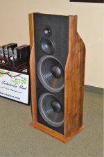
Pano mentioned the sides being uneven to reduce cavity resonances. John used a similar approach on the Widowmaker III (below) although I'm guessing a big part of the wings was to keep the size of the front baffle less wide. He had a tough time selling his speakers as they tended to be pretty large and wide. Sounded great, thought. So on the Manzi it was likely a similar attempt to keep the baffle smaller while keeping the bass intact.
All guesses. It'd be interesting to hear this design compared to the Ultras as they use the same parts.
Maybe Pano has some insight.
The wings likely are to increase the efficiency of the woofer. That makes the speaker easier to drive and perhaps cuts down on crossover parts. John was always trying to design stuff that sounded great and was cheap to build.
Pano mentioned the sides being uneven to reduce cavity resonances. John used a similar approach on the Widowmaker III (below) although I'm guessing a big part of the wings was to keep the size of the front baffle less wide. He had a tough time selling his speakers as they tended to be pretty large and wide. Sounded great, thought. So on the Manzi it was likely a similar attempt to keep the baffle smaller while keeping the bass intact.
All guesses. It'd be interesting to hear this design compared to the Ultras as they use the same parts.
Maybe Pano has some insight.
Attachments
I finished adding the woofer trap to the Ultras. At first, it was a minor difference. I would change the balance from L to R as I listened to tracks. After an hour or two of listening, I am glad I upgraded. I think Pano put it best - there was a bite to the woofer midrange, an edge to it that is tamed using the trap.
Overall, the sound is much more natural and flattens, what seemed to me, a certain midrange frequency peak.

Overall, the sound is much more natural and flattens, what seemed to me, a certain midrange frequency peak.
- Home
- Loudspeakers
- Multi-Way
- Fast, fun, Inexpensive OB project