Certainly using enough drivers in the right configuration allows the directivity and FR to be dictated. It's not simple to get it right trying to get narrow vertical and controlled horizontal. Progress has been made throughout your simulations but the directivity mismatch is still there.Lowering optimization priority of reflections leads to different results/choices but if you use enough driversyou can have it all, at least within a restricted listening window.
There is something to be said for getting the result you want from a simpler setup. I am nowhere near as keen on making an uber complicated active FIR multiway than I would have been a few years ago. I'm trying my own patience waiting to see what I get with a high efficiency two way.Thanks for the GGNTKT reference. Interesting designs on that website; so nice to see real technical specs published. They certainly get the most out of a limited number of drivers. Perhaps I can learn something from that.

@fluid - I appreciate the tough criticism; I wouldn't make progress without it.
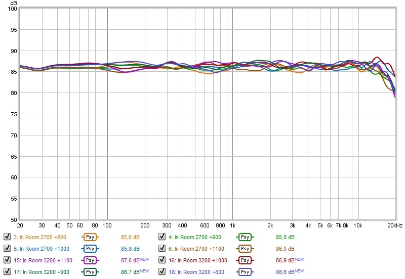
The narrowing/directivity mismatch is on purpose to get rid of monster early reflection circa 320 Hz. If I change the XO to the woofer from 475 Hz to 250 Hz. I get this response:
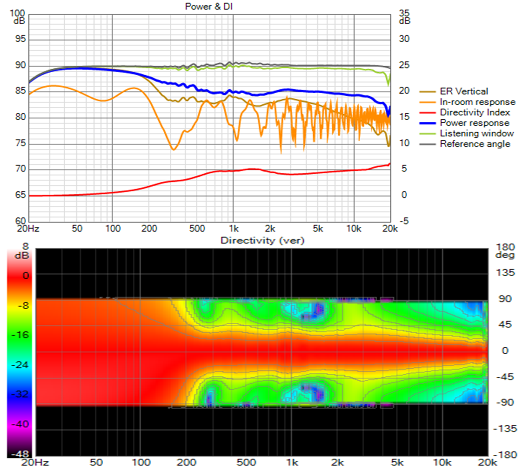
Letting the right amount of energy in the right phase through the bottom woofer and compensating by taking some away from the MTM pairs above it reduces that floor reflection null with little effect on the polar map.
A better job could be done of smoothing the room and power responses at the expense of each other but at this stage I'm satisfied with seeing that it can be done. I wonder what I would do in room where I won't get to see the power response so easily.
These responses are on a waveguide model shortened from 160 mm to 140 mm, which seems to affect only the very high end response. The peaking there in the longer/deeper version has been replaced with a rapid drop off off axis. I don't really believe it; I think the response there is more likely some kind of numerical anomaly as there is a kind of butterfly effect with length. Latest 2 hour abec sim at 120mm indicates I can shorten it further.
Afterthought on simplicity: Reducing the DMA45 array to 8 drivers was a big improvement. The bottom woofer can be left out entirely and replaced with separate sub(s). what one gets is a "top" with a floor reflection null at ~320 Hz with the vertical pattern starting to widen at 500 Hz, as does the H pattern. The purpose of a 3 way is to eliminate that null. I ended up with 4 ways because I chose to add the rim slot array to extend H pattern control an octave lower and eliminate vertical pattern flip for the asymmetric waveguide. Still a little complex for comfort but OK as a science project.
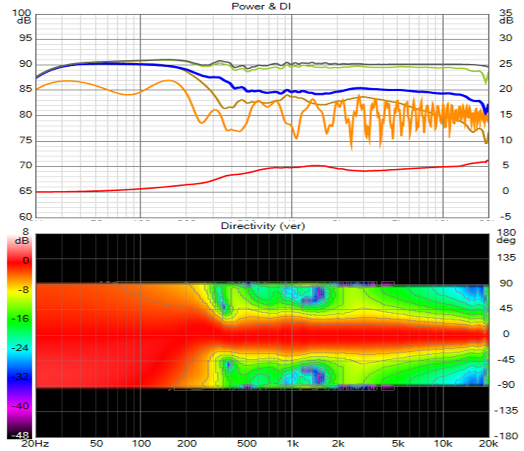
The narrowing/directivity mismatch is on purpose to get rid of monster early reflection circa 320 Hz. If I change the XO to the woofer from 475 Hz to 250 Hz. I get this response:
Letting the right amount of energy in the right phase through the bottom woofer and compensating by taking some away from the MTM pairs above it reduces that floor reflection null with little effect on the polar map.
A better job could be done of smoothing the room and power responses at the expense of each other but at this stage I'm satisfied with seeing that it can be done. I wonder what I would do in room where I won't get to see the power response so easily.
These responses are on a waveguide model shortened from 160 mm to 140 mm, which seems to affect only the very high end response. The peaking there in the longer/deeper version has been replaced with a rapid drop off off axis. I don't really believe it; I think the response there is more likely some kind of numerical anomaly as there is a kind of butterfly effect with length. Latest 2 hour abec sim at 120mm indicates I can shorten it further.
Afterthought on simplicity: Reducing the DMA45 array to 8 drivers was a big improvement. The bottom woofer can be left out entirely and replaced with separate sub(s). what one gets is a "top" with a floor reflection null at ~320 Hz with the vertical pattern starting to widen at 500 Hz, as does the H pattern. The purpose of a 3 way is to eliminate that null. I ended up with 4 ways because I chose to add the rim slot array to extend H pattern control an octave lower and eliminate vertical pattern flip for the asymmetric waveguide. Still a little complex for comfort but OK as a science project.
Attachments
That certainly is a difference here. @nc535 is designing an in-room solution, while all those pretty Klippel results are anechoic based.
Basically working with the room to get an even response there is the big difference between the two.
How much we need the room for excellent stereo replay remains a bigger question. By that I mean how much reflections do we need to hide things like cross talk etc. We've already established arrays uncover that part more that most other speakers. At least that's how I see it. It's both a blessing and a curse, I'd say.
The above proposed 4 way has more in common with conventional solutions (as it does react more with floor/ceiling than the array would*) while keeping enough of a vertical window to cater to both seated as well as standing listening.
(*) as the array would use those reflections to generate a more flat in-room response throughout most of the mid-range.
You know where my money is... (as it was the easiest to try *)
I do realize that reflections can be beneficial. There is a good reason I prefer to add mid-side EQ and a virtual Haas kicker to my arrays. I'm just hoping I can find a controllable answer to that part of the Stereo mystery, without sacrificing other listening positions. The EQ + ambience works very well, but chances are that the shaded array will emphasize this phenomenon (stereo cross talk dips) even more. As it has an even more flat in-room response than the un-shaded array.
30 cm window vertical, 50 cm front to back...
*= I only tried it because I had to store the arrays in my garage for our living room upgrade. It was an opportunity to learn something, or so i hope.
Attachments
Last edited:
Right - anechoically multi-ways seem better than full range line arrays. Measure in room and its reversed. The relative ordering could reverse again with carpeting to absorb everything above 1 khz that hits the floor, if carpeting would indeed do that.
We have respected voices here saying don't worry about those reflections. I can see both sides. The real world picture is vastly more complicated than the simulation Its easy to believe a simulated narrow cancellation null won't be audible; harder when a wide valley remains after smoothing. I can't ignore the fact that 90% or more of speakers that have starred in reviews and preference tests have a structure that indicates sensitivity to the floor.
We have respected voices here saying don't worry about those reflections. I can see both sides. The real world picture is vastly more complicated than the simulation Its easy to believe a simulated narrow cancellation null won't be audible; harder when a wide valley remains after smoothing. I can't ignore the fact that 90% or more of speakers that have starred in reviews and preference tests have a structure that indicates sensitivity to the floor.
My comments are not intended to be tough or as criticism only to point out what I see. I don't have all the answers to what's right far from it.@fluid - I appreciate the tough criticism; I wouldn't make progress without it.
What I see (that I would try and do differently if I was in the same position) relates to the DI. There are three bumps between 200 and 1.5K. They are small and not terrible but they indicate that those individual responses don't really want to join together. The waveguide has a scoop in the DI after that, I would be aiming for that to be flat or rising and it would integrate better with the lower drivers. I imagine you see that yourself anyway.
I agree that designing the speaker to work with the room is totally valid. How exactly to do that based on these simulations and data presentation is less clear. The correlation of measurements to perception is still not totally worked out. I agree that the arrays demonstrate that removing floor and ceiling reflections to a great extent does make the phantom centre problem worse. Just like adding side wall reflections can be both pleasing and distracting.That certainly is a difference here. @nc535 is designing an in-room solution, while all those pretty Klippel results are anechoic based.
Basically working with the room to get an even response there is the big difference between the two.
How much we need the room for excellent stereo replay remains a bigger question. By that I mean how much reflections do we need to hide things like cross talk etc. We've already established arrays uncover that part more that most other speakers. At least that's how I see it. It's both a blessing and a curse, I'd say.
I'm not sure what to make of the orange in room prediction that you are putting a lot of effort into changing. When I played with it I saw that adding more drivers and reflections made it trend to flat. It doesn't seem to be totally representative of reality for a lower number of drivers. The PIR from CTA2034 has been shown to be a pretty good indicator of what will be measured steady state in a room. That is a mix of the different curves not simulated reflections.Right - anechoically multi-ways seem better than full range line arrays. Measure in room and its reversed. The relative ordering could reverse again with carpeting to absorb everything above 1 khz that hits the floor, if carpeting would indeed do that.
We have respected voices here saying don't worry about those reflections. I can see both sides. The real world picture is vastly more complicated than the simulation Its easy to believe a simulated narrow cancellation null won't be audible; harder when a wide valley remains after smoothing. I can't ignore the fact that 90% or more of speakers that have starred in reviews and preference tests have a structure that indicates sensitivity to the floor.
I think with a different waveguide profile the DI of that would look really good.A 3-way is also a possibility if floor reflections don't matter:
An interesting article I came across, an interview with Greg Timbers.
Greg Timbers
I don't agree that blind testing is useless but I do agree that in order to make it easier and ensure a level playing field, the true answer of what is actually best is not being found.
I guess the reason I've focused on boundary reflection nulls is the strength of my recollection of how difficult they made my crossover development for my Synergies using inroom measurements. Turning on reflections carried over from line array simulations where they are needed to model the line array.
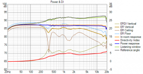
In Vituix, the in-room response without reflection boxes checked is the CTA-2034 PIR. If I uncheck the reflections, I see the PIR overlays the power response curve. If I then equalize the PIR, modelling equalizing an in-room measurement, I get this:
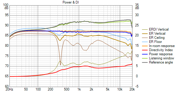
Now the predicted in room response and power response are flat but the axial response rises a total of 8 db over 20 to 20 khz. The reasons it rises is due in part to the waveguide. Thus your comment about the waveguide is right on.
Above 2 khz the waveguide, while flat horizontally, narrows vertically. Below 500 Hz, the system's horizontal pattern gradually widens. Below 200 Hz, the vertical pattern widens quickly. This accounts for the lack of bass and lower midrange in the axial response. Is that problematic? The early reflections that cause it are early enough that it may not be; especially with the speaker tight in a corner.
As to the high end of the spectrum, I've been running sims looking for a better DI within the baffle footprint. The length of the waveguide doesn't affect that. I will look at the Coverage.Angle formula next; suggestions welcome.
In Vituix, the in-room response without reflection boxes checked is the CTA-2034 PIR. If I uncheck the reflections, I see the PIR overlays the power response curve. If I then equalize the PIR, modelling equalizing an in-room measurement, I get this:
Now the predicted in room response and power response are flat but the axial response rises a total of 8 db over 20 to 20 khz. The reasons it rises is due in part to the waveguide. Thus your comment about the waveguide is right on.
Above 2 khz the waveguide, while flat horizontally, narrows vertically. Below 500 Hz, the system's horizontal pattern gradually widens. Below 200 Hz, the vertical pattern widens quickly. This accounts for the lack of bass and lower midrange in the axial response. Is that problematic? The early reflections that cause it are early enough that it may not be; especially with the speaker tight in a corner.
As to the high end of the spectrum, I've been running sims looking for a better DI within the baffle footprint. The length of the waveguide doesn't affect that. I will look at the Coverage.Angle formula next; suggestions welcome.
Attachments
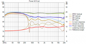
A look at the TD12 3-way equalized the same way.
The TD12 is now as close below the waveguide rim slots as I can get it. This plus lowering the XO to the rim slots almost eliminates the narrowing near crossovers. The DI and power response are as flat as I've seen them, with a 1 db tilt in the axial response to make that happen.
The TD12 is now as close below the waveguide rim slots as I can get it. This plus lowering the XO to the rim slots almost eliminates the narrowing near crossovers. The DI and power response are as flat as I've seen them, with a 1 db tilt in the axial response to make that happen.
Attachments
I know someone stole my branding while I wasn't looking. Now I need a new name if I try an ill fated commercial ventureWhat did I miss?
If I then equalize the PIR, modelling equalizing an in-room measurement, I get this:
Now the predicted in room response and power response are flat but the axial response rises a total of 8 db over 20 to 20 khz. The reasons it rises is due in part to the waveguide. Thus your comment about the waveguide is right on.
The Power response and DI are the inverse of each other so if you EQ the power flat the axial will be the same shape as the DI.
The more asymmetric the shape the harder it is to avoid a scoop in the DI as the frequency goes down. The vertical looses control too early. To closer match the DI in the array sim the overall directivity needs to be higher by a few dB. Narrowing the coverage might get you there.As to the high end of the spectrum, I've been running sims looking for a better DI within the baffle footprint. The length of the waveguide doesn't affect that. I will look at the Coverage.Angle formula next; suggestions welcome.
In your 3 way you might try something closer to a 1:1.2 aspect as you wouldn't be targeting quite such a narrow vertical there.
That does look good for an anechoic style simulation. With a flat DI a little tilt to the on axis is necessary to stop it sounding too bright.The DI and power response are as flat as I've seen them, with a 1 db tilt in the axial response to make that happen.
At 400 x 225 my waveguide has what for most would be an extreme aspect ratio; one I purposely chose for the higher vertically directivity where the waveguide still has control. The rim slot drivers solve the pattern flip problem, taking hold vertically before the waveguide loses control and extending both H and V pattern control. I think they are a game changer.
Spending more time on equalization, I've got the 3-way and 4-way responses looking very much alike, until I enable wall, floor and ceiling reflections. The 4-way is marginally better below 1 khz; beyond that I think the differences don't matter or would disappear with more work on the EQ.
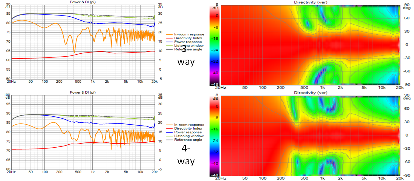
I ask myself: based on this is the extra complexity of the 4-way justified?
Spending more time on equalization, I've got the 3-way and 4-way responses looking very much alike, until I enable wall, floor and ceiling reflections. The 4-way is marginally better below 1 khz; beyond that I think the differences don't matter or would disappear with more work on the EQ.
I ask myself: based on this is the extra complexity of the 4-way justified?
Attachments
Nice dodge . Fortunately I too can escape that question with a better option:
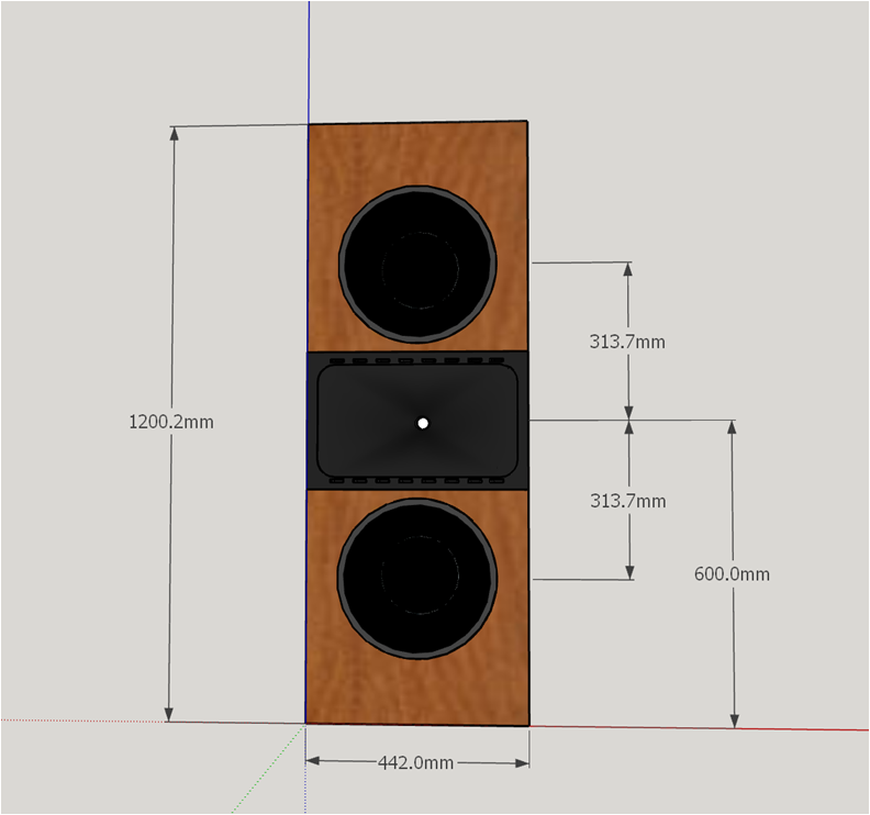
Dual TD12s MTM style has better vertical control as well as smooth DI but its still a 3-way.
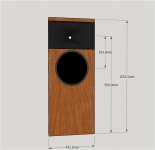
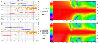
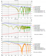
If I keep it down at floor level, which puts waveguide center at the rather low 600mm, the first floor null moves out to 1 khz where one expects such nulls to be filled in by the ambient sound field, reflections, modes,. (Top graph below)
I did the bottom graph because I realized the axial response changes slightly but significantly for seated vs standing. Standing up at 3m some treble is lost but not at 6m (bottom graph below)

If the waveguide center is raised to the original 900mm, the first floor null near seated is at 300 Hz where its harder to treat should treatment prove desirable.
Once again, I see I could have done a better job of equalization but now realize that its because these exported images are stretched vertically compared to those on screen.
. Fortunately I too can escape that question with a better option:Dual TD12s MTM style has better vertical control as well as smooth DI but its still a 3-way.
If I keep it down at floor level, which puts waveguide center at the rather low 600mm, the first floor null moves out to 1 khz where one expects such nulls to be filled in by the ambient sound field, reflections, modes,. (Top graph below)
I did the bottom graph because I realized the axial response changes slightly but significantly for seated vs standing. Standing up at 3m some treble is lost but not at 6m (bottom graph below)
If the waveguide center is raised to the original 900mm, the first floor null near seated is at 300 Hz where its harder to treat should treatment prove desirable.
Once again, I see I could have done a better job of equalization but now realize that its because these exported images are stretched vertically compared to those on screen.
Attachments

If it moves upward to 900, there's room for at least one more woofer, right?
Just kidding...
Seeing how difficult it is to mimic what an array does, I do wonder if the idea I've mentioned a couple of times could actually work. You know, having a Synergy style mid/upper combo in a bass array. It would help if the Synergy could play low I guess. Something like Bushmeister's Synergy with a full range driver at the throat, and big drivers filling in the bottom part. Then the Synergy would be a functional part of the array.
Not curious enough to sim it though. At least not yet.
A synergy includes a waveguide. If you put that waveguide at the center of a vertical array, you then have the problem of matching the H pattern of the waveguide with that of the array. I faced that problem and came up with what I called an H-array, although I didn't define it explicitly in these posts. An H array is two columns of drivers with the cross of the H provided by a waveguide. You don't have to go back very far to see one. The spacing between the two columns is adjusted to match the H patterns.
I found that overlapping the waveguide at center was not a magic bullet to make all the issues go away. Overlap, full or partial can help but it can also be problematic to the extent that it introduces positional dependency. I've gotten good response over a larger volume of space without overlap in the several simulated system configurations that I've tried. In fact I got very good response with my H-array but I judged the system too complex and larger than I wanted to build. What I'm looking at now is an attempt to get almost equally good response in a smaller, simpler package, just giving up vertical control an octave or so earlier in the bass where the room is going to have its way, anyway.
I found that overlapping the waveguide at center was not a magic bullet to make all the issues go away. Overlap, full or partial can help but it can also be problematic to the extent that it introduces positional dependency. I've gotten good response over a larger volume of space without overlap in the several simulated system configurations that I've tried. In fact I got very good response with my H-array but I judged the system too complex and larger than I wanted to build. What I'm looking at now is an attempt to get almost equally good response in a smaller, simpler package, just giving up vertical control an octave or so earlier in the bass where the room is going to have its way, anyway.
A Synergy like the one I linked to, is capable enough to play (real) low. Then it would be fine in an array, which only task would be to support that multi entry horn on the bottom end. That's about as far as I would go, to match an array and Synergy. I'd worry about the differences in drop of per distance, the bass area being somewhat more forgiving and room dominated there anyway.
I didn't mean to offer that remark (Synergy + array) as a substitute for what you tried to do or accomplish here. I'd be rooting for more simple solutions, which more often than not, turn out to be complex enough.
I didn't mean to offer that remark (Synergy + array) as a substitute for what you tried to do or accomplish here. I'd be rooting for more simple solutions, which more often than not, turn out to be complex enough
.- Home
- Loudspeakers
- Full Range
- Full range line array for wall or corner placement