What is that "professional" unit?
No idea, it was an image on Pinterest. Just Google ‘DML Loudspeaker’ or ‘NXT’
and browse the images.
Testing materials
This is just a quick update on how I plan on testing panel materials.
I am not aiming for an absolutist measurement or subjective study at this point, just a comparative look see at the differences in the listening environment I have in the UK. This is a normal room 5m by 4m with the usual clutter, a sofa, bookshelves, carpeting hard wall surfaces.
Test panels will be 430mm by 300 mm without rounding the corners.
Why?
Well the first test material is 2mm Carbon Fibre and thats how that sheet comes. I don't want to sacrifice the sheet for some quick tests as CF is expensive, so I will cut ply and XPS panels to the same spec so they are comparable.
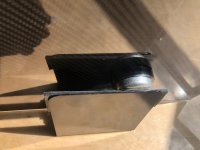
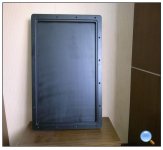
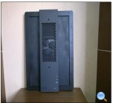
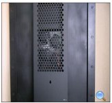
I have an L bracket as a stand with the panel standing on a soft polymer pad with the exciter resting against a soft polymer pad.
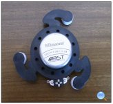
The exciter will the the Tectonics TEAX32C20-8 I bought before the Daytons.
The spec for this exciter can be viewed here. TEAX32C20-8 - Tectonic | Tectonic.
The exciter has been modded to remove the foam outer ring as recommended.
This mod does make a noticeable difference.
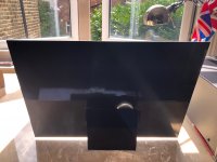
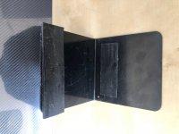
There are pictures below of the CF panel and the stand.
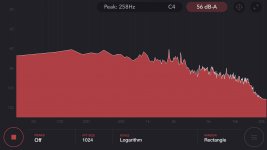
I am alway a bit impatient during development so while I cobbled this together I could not resist a quick white noise test measured using that dB app I found , image also below. I was surprised to see not that much of a difference between CF and the ply I have been using but thats a very quick test and you should not take much notice of that at this stage. When I have finished with all the materials I will post a proper comparison with measurements and subjective impressions.
I also could not resist a quick listen using a few tracks I know well. CF sounds great. Brighter than ply but with great clarity and lots of detail. I see no reason not to include CF at 2mm as a viable material, although it is very expensive compared to ply.
It does look very cool though.
This is just a quick update on how I plan on testing panel materials.
I am not aiming for an absolutist measurement or subjective study at this point, just a comparative look see at the differences in the listening environment I have in the UK. This is a normal room 5m by 4m with the usual clutter, a sofa, bookshelves, carpeting hard wall surfaces.
Test panels will be 430mm by 300 mm without rounding the corners.
Why?
Well the first test material is 2mm Carbon Fibre and thats how that sheet comes. I don't want to sacrifice the sheet for some quick tests as CF is expensive, so I will cut ply and XPS panels to the same spec so they are comparable.
I have an L bracket as a stand with the panel standing on a soft polymer pad with the exciter resting against a soft polymer pad.
The exciter will the the Tectonics TEAX32C20-8 I bought before the Daytons.
The spec for this exciter can be viewed here. TEAX32C20-8 - Tectonic | Tectonic.
The exciter has been modded to remove the foam outer ring as recommended.
This mod does make a noticeable difference.
There are pictures below of the CF panel and the stand.
I am alway a bit impatient during development so while I cobbled this together I could not resist a quick white noise test measured using that dB app I found , image also below. I was surprised to see not that much of a difference between CF and the ply I have been using but thats a very quick test and you should not take much notice of that at this stage. When I have finished with all the materials I will post a proper comparison with measurements and subjective impressions.
I also could not resist a quick listen using a few tracks I know well. CF sounds great. Brighter than ply but with great clarity and lots of detail. I see no reason not to include CF at 2mm as a viable material, although it is very expensive compared to ply.
It does look very cool though.
Attachments
I don't know if this will help you but I built a DML CBT array. The panels are 76 mm wide x 1524 mm tall. Despite the narrow width of the panels, the height of the DML panel generates low frequencies. I believe width -- a rectangular shape -- supplies higher sound volume levels with fewer exciters. There is some research that investigates multi-actuator panel (MAP) and where to locate actuators on the panel to optimize the panel modes. There is also research on using MAP arrays for wave field synthesis. I think they used a maximum distance of seven inches between actuators in their panel arrays. However, that distance changes based on panel geometry and panel material dampening.
Project: CBT array, balanced DML, delay curved
Project: CBT array, balanced DML, delay curved
DML listening test for Foam board, Ply and carbon Fibre
Listening tests for DML materials.
Sorry but this is a long post. I hope you all find it useful.
As promised here are my notes from testing materials. I will try a couple more next weekend.
Playlist
Baby Plays Around 3.11 Declan Mcmanus and Cait O’Roirdan
Bitter Sweet Symphony 3.53 London Grammer Live at the BBC
Born to Die 4:46 Lana Del Rey Born to Die
Rain so Hard 5.45 Otis Taylor Otis People
Letters from the 9th Ward 4.46 Rickee Lee Jones -(Walk away Renee)
Tom’s Diner 2.09 Suzanne Vega Solitude Standing
The Lark Ascending 6.04 Ralph Vaughn Williams- Sir Andrew Davies BBC Symphony Orchestra
Evening of Roses 2.59 (Arr. Cello, Clarinet and Assembly ) Josef Hader.
Playback via MacPro/TIDAL/Copland CTA405 valve Integrated amp/Tectonic TEAX32C20-8 High Power Exciter
Three materials tested Foamboard 5mm/ Birch Ply 3mm/ Carbon Fibre 2mm all 430mm by 300 mm rectangles with sharp corners.
All listening was full range with no eq applied and at the same amp volume.
Foam board 5mm
This one was a big surprise but not in a good way.
Strong 'cardboard’ colouration
Very bright presentation
Loud!
Frankly so bad I abandoned the test. Maybe just this sample?
So bad I will repeat the test with another foam type- e.g. XPS or EPS
Birch Ply 3mm ‘Laserboard’
+ves
Detailed and clear sound. Fuller frequency range than foam board - harmonically richer
Percussion instruments e.g. piano, very clear definition- sharp leading edge to notes and rich timbre
Highs very clear- e.g. violin in ‘Lark Ascending’
String sounds very clear definition - timbre and harmonic richness, raspy sonorous Cello’s ,
Woodwind the same
Banjo sounds ( e.g. Otis Taylor track) have bite and metallic resonance
-ves
Some bass on some tracks.Well defined but no slam or weight.
Being super critical maybe some light coloration e.g slightly ‘cuppy’ on some female vocals e.g, on ‘Tom’s Diner’ ?
Possibly slightly compressed.
Carbon Fibre 2mm
+ves
Best frequency balance of the three reaching lower and no overt coloration. Better bass, more of it than the ply panel.
Great clarity- reveals an overall coloration in ply which is a mid range ‘sheen’ . This is slight but obvious in comparison with the CF panel.
Cleanest female vocals - clarity and fullness
Brass nice and raspy.
Percussion instruments clear, piano sounds full bodied.
Cello full bodied and resonant
High end clear violin again on ‘Lark Ascending’
-ve
Possibly slightly thin balance?
So on this very casual test Carbon Fibre is a clear winner. Ply is also very good and with eq can have its mid colouration dialled out. Foam board was a big surprise as it is frequently highly recommended. I will try Foam board again with another batch next weekend as it performed so badly there must be a problem with this sheet.
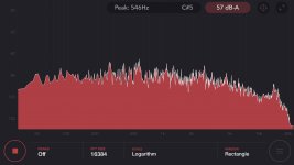
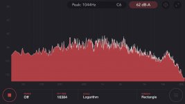
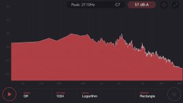
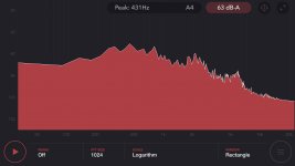
P.S. A note on the images. The images included below are frequency responses based on white noise recorded at 1 metre using the dB App. Image order is 1) Foam board 2) Ply 3) Carbon Fibre
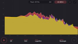
I have also included 4) a composite overlay of the responses for the three panels. Foam board is Red, Ply is Purple, CF is Yellow.
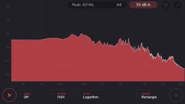
I have also included two additional high res frequency responses I repeated this morning 5) Ply 6) Carbon Fibre.
Listening tests for DML materials.
Sorry but this is a long post. I hope you all find it useful.
As promised here are my notes from testing materials. I will try a couple more next weekend.
Playlist
Baby Plays Around 3.11 Declan Mcmanus and Cait O’Roirdan
Bitter Sweet Symphony 3.53 London Grammer Live at the BBC
Born to Die 4:46 Lana Del Rey Born to Die
Rain so Hard 5.45 Otis Taylor Otis People
Letters from the 9th Ward 4.46 Rickee Lee Jones -(Walk away Renee)
Tom’s Diner 2.09 Suzanne Vega Solitude Standing
The Lark Ascending 6.04 Ralph Vaughn Williams- Sir Andrew Davies BBC Symphony Orchestra
Evening of Roses 2.59 (Arr. Cello, Clarinet and Assembly ) Josef Hader.
Playback via MacPro/TIDAL/Copland CTA405 valve Integrated amp/Tectonic TEAX32C20-8 High Power Exciter
Three materials tested Foamboard 5mm/ Birch Ply 3mm/ Carbon Fibre 2mm all 430mm by 300 mm rectangles with sharp corners.
All listening was full range with no eq applied and at the same amp volume.
Foam board 5mm
This one was a big surprise but not in a good way.
Strong 'cardboard’ colouration
Very bright presentation
Loud!
Frankly so bad I abandoned the test. Maybe just this sample?
So bad I will repeat the test with another foam type- e.g. XPS or EPS
Birch Ply 3mm ‘Laserboard’
+ves
Detailed and clear sound. Fuller frequency range than foam board - harmonically richer
Percussion instruments e.g. piano, very clear definition- sharp leading edge to notes and rich timbre
Highs very clear- e.g. violin in ‘Lark Ascending’
String sounds very clear definition - timbre and harmonic richness, raspy sonorous Cello’s ,
Woodwind the same
Banjo sounds ( e.g. Otis Taylor track) have bite and metallic resonance
-ves
Some bass on some tracks.Well defined but no slam or weight.
Being super critical maybe some light coloration e.g slightly ‘cuppy’ on some female vocals e.g, on ‘Tom’s Diner’ ?
Possibly slightly compressed.
Carbon Fibre 2mm
+ves
Best frequency balance of the three reaching lower and no overt coloration. Better bass, more of it than the ply panel.
Great clarity- reveals an overall coloration in ply which is a mid range ‘sheen’ . This is slight but obvious in comparison with the CF panel.
Cleanest female vocals - clarity and fullness
Brass nice and raspy.
Percussion instruments clear, piano sounds full bodied.
Cello full bodied and resonant
High end clear violin again on ‘Lark Ascending’
-ve
Possibly slightly thin balance?
So on this very casual test Carbon Fibre is a clear winner. Ply is also very good and with eq can have its mid colouration dialled out. Foam board was a big surprise as it is frequently highly recommended. I will try Foam board again with another batch next weekend as it performed so badly there must be a problem with this sheet.
P.S. A note on the images. The images included below are frequency responses based on white noise recorded at 1 metre using the dB App. Image order is 1) Foam board 2) Ply 3) Carbon Fibre
I have also included 4) a composite overlay of the responses for the three panels. Foam board is Red, Ply is Purple, CF is Yellow.
I have also included two additional high res frequency responses I repeated this morning 5) Ply 6) Carbon Fibre.
Attachments
Last edited:
Have you seen the Billionsound sub woofers?
http://www.billionsound.com/products_detail/productId=379.html
Here's a composite style with brief discussion of MAPs. He includes research paper citations at the bottom of the post.
Jose J. Lopez | Home page
Now, the one thing Dr Lopez says that I think he gets wrong is low frequencies in living rooms. Much of the MAP research was intended for live sound reproduction. It was intended for large rooms and venues. Earl Geddes and others proved long ago that low frequencies in small rooms are modal, similar to a DML. Depending on the size of your room you don't need a DML with good low frequency response. So you wouldn't operate under the restrictions Dr. Lopez notes.
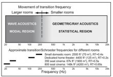
Instead, you'd have two systems of DML speakers in a small room. One designed for ray acoustics and one designed for modal acoustics, separated by the Schroeder transition region frequencies.
Basically, if your goal is small room listening, you want a material and geometry that works well above your transition region. Then you'd want a material and geometry that works well below the transition frequency. Finally, you'd locate and equalize the two systems using different techniques, one for ray acoustics and one for modal acoustics. Which is a godsend because trying to find only one material and only one geometry to cover the entire frequency spectrum is hard and forces too many compromises.
http://www.billionsound.com/products_detail/productId=379.html
Here's a composite style with brief discussion of MAPs. He includes research paper citations at the bottom of the post.
Jose J. Lopez | Home page
Now, the one thing Dr Lopez says that I think he gets wrong is low frequencies in living rooms. Much of the MAP research was intended for live sound reproduction. It was intended for large rooms and venues. Earl Geddes and others proved long ago that low frequencies in small rooms are modal, similar to a DML. Depending on the size of your room you don't need a DML with good low frequency response. So you wouldn't operate under the restrictions Dr. Lopez notes.
Instead, you'd have two systems of DML speakers in a small room. One designed for ray acoustics and one designed for modal acoustics, separated by the Schroeder transition region frequencies.
Basically, if your goal is small room listening, you want a material and geometry that works well above your transition region. Then you'd want a material and geometry that works well below the transition frequency. Finally, you'd locate and equalize the two systems using different techniques, one for ray acoustics and one for modal acoustics. Which is a godsend because trying to find only one material and only one geometry to cover the entire frequency spectrum is hard and forces too many compromises.
Attachments
Have you seen the Billionsound sub woofers?
http://www.billionsound.com/products_detail/productId=379.html
Here's a composite style with brief discussion of MAPs. He includes research paper citations at the bottom of the post.
Jose J. Lopez | Home page
Now, the one thing Dr Lopez says that I think he gets wrong is low frequencies in living rooms. Much of the MAP research was intended for live sound reproduction. It was intended for large rooms and venues. Earl Geddes and others proved long ago that low frequencies in small rooms are modal, similar to a DML. Depending on the size of your room you don't need a DML with good low frequency response. So you wouldn't operate under the restrictions Dr. Lopez notes.
Instead, you'd have two systems of DML speakers in a small room. One designed for ray acoustics and one designed for modal acoustics, separated by the Schroeder transition region frequencies.
Basically, if your goal is small room listening, you want a material and geometry that works well above your transition region. Then you'd want a material and geometry that works well below the transition frequency. Finally, you'd locate and equalize the two systems using different techniques, one for ray acoustics and one for modal acoustics. Which is a godsend because trying to find only one material and only one geometry to cover the entire frequency spectrum is hard and forces too many compromises.
Thank you for the information Bradley. It will be a while before I get to that level of sophistication! I tried the links, thank you for them, unfortunately the
billionsound site is so slow it times out for me so if you have another source I would be grateful.
Billionsound supplies Dayton branded exciters. It's a Chinese web site so maybe that's why it's taking a long time to load. It's an interesting site to browse when you're building DMLs.
sub woofer Geometry: 750x550x85mm
Exciters: 6 exciters, 100-150W
sub woofer Geometry: 750x550x85mm
Exciters: 6 exciters, 100-150W
Attachments
Besides what I said about the outer support ring on the tectonic exciter I think I know the problem to your dilemma. I agree with the larger contact area allows more transition of energy but there is another aspect that differs in certain exciters which is not available in the statistics which is Xmax. Certain Dayton exciters have higher excursion then the Tectonics exciters. I found this out through hands on experience when experimenting with my DML BASS panel using a sub amp. Certain Dayton exciters have more pistonic motion while the tectonics have less pistonic motion. Less pistonic motion means less out put in the lower frequencies. At higher frequencies the motion becomes more modal like a conventional cone/dome tweeter.
This is why at higher volumes when playing a track with a lot of low frequencies the Tectonics distort more then the Daytons plus the Daytons can handle twice the amount of watts so they can play louder with less distortion.
DMLBES,
From all the insight and advice (like above) you have shared, I gather you have built several (or more) DMLs yourself. Is that correct? Could you share some of the details of your favorite designs? If you have already done so, can you point me to the link or post?
Thanks,
Eric
Has anyone tried placing the exciter near the corner of the panel? I'm still wrapping my head around this DML concept, but my (perhaps naive) impression is that you would want to be able to drive as many vibration modes of the panel as possible, and as equally as possible. In that case, the worst possible location of the exciter would be at the center, because many (probably most!) of the possible vibration modes have nodes in the center and hence would not be driven by placing the exciter there. And the relatively few modes without a node there would be driven very well, perhaps too well. And I see that center placement is usually not recommended, so that makes sense.
On the other hand, very few modes have nodes near the corner of the panel, so nearly all available modes would be very well driven by corner placement. So corner placement seems like a good idea to me. Since nobody does it (as far as I can tell), probably it's a bad idea. But has anyone tried it and what happened?
On the other hand, very few modes have nodes near the corner of the panel, so nearly all available modes would be very well driven by corner placement. So corner placement seems like a good idea to me. Since nobody does it (as far as I can tell), probably it's a bad idea. But has anyone tried it and what happened?
Last edited:
What if you reverse the polarity of the connections on the two exciters? I think you'd double (not cancel) both the drive (and mass) effect, no?Exciters work like Dipoles similar to Open Baffle speakers where the front and back of the panels are out of phase. So adding another exciter on the opposite side of the panel could cancel each other out.
Eric
DMLBES,
From all the insight and advice (like above) you have shared, I gather you have built several (or more) DMLs yourself. Is that correct? Could you share some of the details of your favorite designs? If you have already done so, can you point me to the link or post?
Thanks,
Eric
Yes through out the years I have built many prototype DML panels.
My favorite designs are ones that use a Frame to support the panel material and a brace/spline to support the exciter in place. They are basically Floor standing DML panels, instead of the hanging from the ceiling by a string.
My favorite designs are ones that use a Frame to support the panel material and a brace/spline to support the exciter in place. They are basically Floor standing DML panels, instead of the hanging from the ceiling by a string.
Thanks. Do you prefer supports for the panel that provide fixed supports (that resist only displacement) or clamped supports (that resist both displacement and rotation)? I can imagine that the choice might influence the size of the ideal panel. Is that correct?
Do I understand correctly that your spline (supporting the exciter) is rigidly attached to the frame that supports the panel?
What do you think of frames curved along one axis? I have seen this curvature suggested (but not explained) in a few sources. I think such curvature would effectively reduce the number of available vibration modes (negative?) , but would allow the use of relatively thinner membranes, which (without being confined to curved frames) could warp over time and hence change their response.
Your thoughts would be appreciated,
Thanks,
Eric
Panel material (EPS,XPS,etc.) is attached to the frame by some type of foam, rubber, cloth, which acts as the surround to hold the panels in place. Its no different then the surround material of a conventional cone driver that attaches the diaphragm to the basket.
Yes the spline is rigidly attached to the frame to hold and support the exciters magnet in place. Very similar to how a conventional cone speakers "basket" holds the magnet in place.
When using a frame and a spline together the design is basically that of a BMR driver but on a way larger scale as most BMR drivers are under 4inches.
I don't know about curved frames as I have not ventured in that direction. One thing about these panels is that the designs are endless and everyone will have a preferred or favorite design.
I'm close to jumping in and trying a set of DMLs.
The exciter of choice seems to be the DAEX32U-4. Only problem is that my Yamaha RX-V485 AVR is spec'd for minimum 6 ohm drivers and 80 watts max (at 8 ohms). Since the Daytons are only 20 watts, would my amp be okay with these exciters?
Alternatively, I could put two of the Daytons on each panel and wire them in series. When mounting two exciters on a single panel, what pair of locations have others found to work well?
Or are there 8 ohm exciters that folks have had as much luck as the Daytons?
Thanks,
Eric
I've seen the idea of FEM modeling of modes mentioned in several threads about DML speakers. But I haven't come across any where anybody actually examined it. Has anyone tried this and reported on it?
It seems like there should be a relationship between the mode shapes/frequencies of the natural vibration modes of the panels and the resulting SPL output. But is there? And if so, what are the relationships and what do they tell us about how to design panels?
Eric
It seems like there should be a relationship between the mode shapes/frequencies of the natural vibration modes of the panels and the resulting SPL output. But is there? And if so, what are the relationships and what do they tell us about how to design panels?
Eric
I'm close to jumping in and trying a set of DMLs.
The exciter of choice seems to be the DAEX32U-4. Only problem is that my Yamaha RX-V485 AVR is spec'd for minimum 6 ohm drivers and 80 watts max (at 8 ohms). Since the Daytons are only 20 watts, would my amp be okay with these exciters?
Alternatively, I could put two of the Daytons on each panel and wire them in series. When mounting two exciters on a single panel, what pair of locations have others found to work well?
Or are there 8 ohm exciters that folks have had as much luck as the Daytons?
Thanks,
Eric
Hi Eric.
The DAEX32U-4. are 40 Watts according to the specs I have read. By experimentation by users on various sites the best position for the first exciter is two fifths of the width and length. You can place a second exciter close to the first and it will work. Others more experienced in DML’s will no doubt be along soon.
I'm close to jumping in and trying a set of DMLs.
The exciter of choice seems to be the DAEX32U-4. Only problem is that my Yamaha RX-V485 AVR is spec'd for minimum 6 ohm drivers and 80 watts max (at 8 ohms). Since the Daytons are only 20 watts, would my amp be okay with these exciters?
Alternatively, I could put two of the Daytons on each panel and wire them in series. When mounting two exciters on a single panel, what pair of locations have others found to work well?
Or are there 8 ohm exciters that folks have had as much luck as the Daytons?
Thanks,
Eric
A while back there were a lot of issues with the Ultra exciter failing. Not sure if that problem has been resolved.
Most of the good sounding exciters are 4ohms, I don't know why Dayton doesn't make 8ohm versions of there 4ohm exciters as majority of standard receivers are usually 8ohms.
One of the best bang for buck exciter is the Dayton DAEX25FHE-4. (wish they made a 8ohm version)
Standard location placement is the 2/5 , 3/5 as stated in the Dayton guide to exciters. BUT it is also DESIGN dependent as best location is what your own EARS prefer.
Thanks guys, I just ordered 4 of each of the 32U-4 ultras and 25FHE-4s. The FHE's are on back order so it looks like I'll be playing with the ultras first.
With respect to the placement, thanks for the suggestions. For sure I will try lots of different locations. I've seen the 2/5 recommendation before so I did plan to try that for certain initially.
I suppose that the 2/5 recommendation came from someone's trial and error anyway. But I do find the placement question to be an interesting one. My gut feeling would be that you would want to drive as many of the bending modes of the panel as possible. And in that case the panel corner would likely be the best candidate location. But nobody seems to recommend that, so I must be missing something! But I'll try and find out what..
Eric
- Home
- Loudspeakers
- Full Range
- A Study of DMLs as a Full Range Speaker