Thank you DMLBES, that is an aspect I had not considered. its on the list for experimentation. On the 2 ft space that is not an option for me in the UK as the WAF would turn steeply negative.
I received the Dayton exciters today and will begin to experiment with them over the weekend.
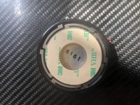
One of the things I want to do first is a small mod to the spring steel spiders you can see in the photo attached. With the Daytons on the panels in France I noticed the spiders would ring at certain frequencies. This was not noticeable with music but I did a few frequency sweeps and they really take off when you reach their resonance point. I am going to damp them with a small line of silicon sealant mid point on each arc.
Burnt
Attachments
I see carbon fibre....new DML sheet material? They would look great. Low mass and stiff indeed!
So this is the first feedback on the tests I have been trying this weekend.
All I have tried so far is swapping out the exciters and the Daytons are a much better match with the panels I have. As a reminder this is a 3mm thick birch ply panel 600mm by 1200mm.
I stress the Daytons are a better match to the panels I have. This is not to criticise the Tectonic exciters in anyway. I note that the Tectonic exciters are usually used in multiples of up to 4 on the Pro-panels I have seen and I have no reason to believe that a similar arrangement might not work fine on a panel the size and material density I have. Certainly to my ears there appears to be a volume threshold below which I get a lower quality sound using a single Tectonic. Above that and the Tectonics sound acceptable if not a good as the Daytons. The Tectonics also run into distortion problems at high output levels that the Daytons cope with happily. I think multiple Tectonic exciters would not exhibit this limit.
So how do you explain it?
This is just a hunch and needs to be taken with a bucket of salt but I think it might be how well the exciters are able to transmit energy to the panel. The contact area of the Tectonics exciter is about half of that of the Dayton exciter ( 51% by calculation) which might be a factor. In addition to that the Tectonic masses 150g, there is no figure given in the Dayton spec sheet but it feels a little heavier using the patented BurnCoil juggled mass method. This mean a bit more 'resistance mass' to the reaction force as currently the exciters a free mounted and do not have the benefit of a strut to support the rear.
Then there is the motor design where, surprisingly, the Tectonic has better numbers if I am reading them right. The 'Force factor" or BL for the Tectonic is 76% higher for the Tectonic exciter so for a given voltage it should generate more energy. Bit of a puzzle that one.
Then there is DMLBES's suggestion that the support ring on the Tectonic is a bit of a design flaw and needs to be removed. It needs to be explored, but if you will forgive me I am going to save irreversible mods until a little latter.
I stress that multiple Tectonics might work fine with large relatively dense panels and using a smaller lighter panel might suite a single Tectonic exciter just fine.
Next up
- Dealing with rear reflection
- Alternative panel materials- including CF jimk04
Getting there, but the French panels maintain their edge at the moment, by a margin.
Last edited:
Just to add that there are differences between the motor design that might compensate for the difference in BL. The Tectonic exciter is an 8ohm coil whereas the Dayton is a nominal 4ohm. Force is provided by BLI so as the current flow will be higher in the Dayton that means the two motors real world performance may be very similar, which leaves the contact area as the most significant differentiator, maybe.
Sorry xrk971 just catching up. No I am still using the birch ply. Carbon Fibre is further down the road.
Just add that the Dayton’s have improved after a day just like the ones in France. Definitely a running in period applies to new ones. Currently much happier with the sound.
Just add that the Dayton’s have improved after a day just like the ones in France. Definitely a running in period applies to new ones. Currently much happier with the sound.
Hello BurntCoil
Have you considered attempting to make a frame to put the ply panel under pressure to the point where it bows slightly? Not too much so contact still occurs but enough to reduce the panels ability to freely flex.
Would be very interested into what you feel so far would be the ideal transducer design.
Paul
Paul there is a German manufacturer who tensions a spruce panel by bending. The claim is that this creates a ‘soundboard’ effect somewhat like a guitar or violin soundboard. He seems to get good results. I believe another contributor, CLS, has had success by curving foam board to gain a similar effect. This is something I might experiment with latter but I have a lot to do first.
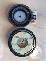
On exciter designs this is an area I am thinking about but not ready to share yet because I don't know enough at this point. I will say from what I have experienced to date that the Dayton driver has some lateral and neat solutions to a few needs, e.g. the use of a spiral cut spring steel disc as a spider which is flexible along the voice coil centre axis but stiff radially providing good support to the exciter mass. This has its problems still, I use a blob of silicon on each arm to suppress resonances, but it is an elegant solution to supporting the exciter mass rather than the spider arms used in earlier designs and the Tectonic concentric ring approach to self supporting.
I also think that exciter contact area is important. Larger contact area seems to couple better with the panel, hardly a revelation, and allows the transition of more energy from the exciter to the panel.
Have a look at the photo attached and see what you think.
I will post more thoughts on exciters when I am through confusing myself and have something useful to add.
Cheers
Burnt.
Attachments
So this is the first feedback on the tests I have been trying this weekend.
All I have tried so far is swapping out the exciters and the Daytons are a much better match with the panels I have. As a reminder this is a 3mm thick birch ply panel 600mm by 1200mm.
I stress the Daytons are a better match to the panels I have. This is not to criticise the Tectonic exciters in anyway. I note that the Tectonic exciters are usually used in multiples of up to 4 on the Pro-panels I have seen and I have no reason to believe that a similar arrangement might not work fine on a panel the size and material density I have. Certainly to my ears there appears to be a volume threshold below which I get a lower quality sound using a single Tectonic. Above that and the Tectonics sound acceptable if not a good as the Daytons. The Tectonics also run into distortion problems at high output levels that the Daytons cope with happily. I think multiple Tectonic exciters would not exhibit this limit.
So how do you explain it?
This is just a hunch and needs to be taken with a bucket of salt but I think it might be how well the exciters are able to transmit energy to the panel. The contact area of the Tectonics exciter is about half of that of the Dayton exciter ( 51% by calculation) which might be a factor. In addition to that the Tectonic masses 150g, there is no figure given in the Dayton spec sheet but it feels a little heavier using the patented BurnCoil juggled mass method. This mean a bit more 'resistance mass' to the reaction force as currently the exciters a free mounted and do not have the benefit of a strut to support the rear.
Then there is the motor design where, surprisingly, the Tectonic has better numbers if I am reading them right. The 'Force factor" or BL for the Tectonic is 76% higher for the Tectonic exciter so for a given voltage it should generate more energy. Bit of a puzzle that one.
Then there is DMLBES's suggestion that the support ring on the Tectonic is a bit of a design flaw and needs to be removed. It needs to be explored, but if you will forgive me I am going to save irreversible mods until a little latter.
I stress that multiple Tectonics might work fine with large relatively dense panels and using a smaller lighter panel might suite a single Tectonic exciter just fine.
Next up
- Dealing with rear reflection
- Alternative panel materials- including CF jimk04
Getting there, but the French panels maintain their edge at the moment, by a margin.
Besides what I said about the outer support ring on the tectonic exciter I think I know the problem to your dilemma. I agree with the larger contact area allows more transition of energy but there is another aspect that differs in certain exciters which is not available in the statistics which is Xmax. Certain Dayton exciters have higher excursion then the Tectonics exciters. I found this out through hands on experience when experimenting with my DML BASS panel using a sub amp. Certain Dayton exciters have more pistonic motion while the tectonics have less pistonic motion. Less pistonic motion means less out put in the lower frequencies. At higher frequencies the motion becomes more modal like a conventional cone/dome tweeter.
This is why at higher volumes when playing a track with a lot of low frequencies the Tectonics distort more then the Daytons plus the Daytons can handle twice the amount of watts so they can play louder with less distortion.
Thanks DMLBES that makes perfect sense. It would be interesting to test how much energy is imparted to a panel per volt of input. That would be loudness but there may be a frequency threshold where modal operation occurs?
I just recently heard about Distributed Mode Loudspeakers and it sounds quite interesting. I've been trying to read up on it and find some guidelines.
Being an thinker I prefer to have things planned before I consider starting so I am looking for some guidance here on whether my findings are at all accurate.
Sources
Sound Solutions Vol. 2: Building a Simple 2'x2' Distributed Mode Loudspeaker
DML Flat Panel | Parts Express Project Gallery
DIY Distributed Mode Loudspeaker | HiFiVision.com
Materials
The board
Firstly, the materials suggested seem to range from Carbon Fiber, to Plywood to Balsa wood and XPS Styrofoam.
I've been looking at Styrofoam, more specifically This sheet of XPS (2400x600x20 mm)
STYROFOAM 300 BE-A-N 423-020 | Beijer Byggmaterial
I've seen several build from 1" thick styrofoam but this being Sweden we only do inches for lumber and nails.
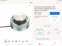
Driver
Dayton Audio DAEX32U-4 Ultra 32mm Exciter 20W 4 Ohm
The listed driver has been mentioned in several builds related to XPS.
Plans
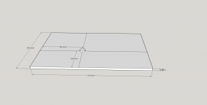
So, what dimensions to use?
I think using the full width is a good start. But how long should it be? I saw someone mention the golden ratio, so I multiplied the width of 600mm with the golden ratio. This means my board will be
600*970
Placement of the driver has been a bit less specific, but I think I saw someone mention 2/5 from the edges. I've drawn an image to show how what this would mean in my case.
I am not sure what is up or down, nor do I know whether the left speaker has its driver away from the right speaker.
Treatment
As far as I understand, the XPS needs to be sanded on both the flat sides to remove the outer layer. they should also be rounded around the edges in accordance with the first link amongst my sources.
They are then to be treated with a 1:1 mix of water and wallpaper glue.
Questions
Are my plans anywhere near valid?
do I mirror the left and right speakers?
Will they work ok with my Nad 356BEE?
Can I just screw these in at the top to get mounting points or do I need to reconsider? https://www.jula.se/catalog/bygg-och-farg/beslag/inredningsbeslag/skruvkrokar/skruvkrokar-313509/
Please ignore the lines on the drawing, they are only there to help me with placing the driver.
Being an thinker I prefer to have things planned before I consider starting so I am looking for some guidance here on whether my findings are at all accurate.
Sources
Sound Solutions Vol. 2: Building a Simple 2'x2' Distributed Mode Loudspeaker
DML Flat Panel | Parts Express Project Gallery
DIY Distributed Mode Loudspeaker | HiFiVision.com
Materials
The board
Firstly, the materials suggested seem to range from Carbon Fiber, to Plywood to Balsa wood and XPS Styrofoam.
I've been looking at Styrofoam, more specifically This sheet of XPS (2400x600x20 mm)
STYROFOAM 300 BE-A-N 423-020 | Beijer Byggmaterial
I've seen several build from 1" thick styrofoam but this being Sweden we only do inches for lumber and nails.
Driver
Dayton Audio DAEX32U-4 Ultra 32mm Exciter 20W 4 Ohm
The listed driver has been mentioned in several builds related to XPS.
Plans
So, what dimensions to use?
I think using the full width is a good start. But how long should it be? I saw someone mention the golden ratio, so I multiplied the width of 600mm with the golden ratio. This means my board will be
600*970
Placement of the driver has been a bit less specific, but I think I saw someone mention 2/5 from the edges. I've drawn an image to show how what this would mean in my case.
I am not sure what is up or down, nor do I know whether the left speaker has its driver away from the right speaker.
Treatment
As far as I understand, the XPS needs to be sanded on both the flat sides to remove the outer layer. they should also be rounded around the edges in accordance with the first link amongst my sources.
They are then to be treated with a 1:1 mix of water and wallpaper glue.
Questions
Are my plans anywhere near valid?
do I mirror the left and right speakers?
Will they work ok with my Nad 356BEE?
Can I just screw these in at the top to get mounting points or do I need to reconsider? https://www.jula.se/catalog/bygg-och-farg/beslag/inredningsbeslag/skruvkrokar/skruvkrokar-313509/
Please ignore the lines on the drawing, they are only there to help me with placing the driver.
Attachments
Anyone tried these?
Very interesting thread......
I bought a pair of these to experiment with and have got them bonded to some 3mm thick hardboard panels that I happen to have at hand. The panels are about 1.2 m x 0.6 m Not ideal, but I put a radius on each corner and have them hung horizontally away from a wall and separated by a meter or so.
Impressions? Very interesting sound field and I have to say that the sound quality is way beyond what I was expecting. They are light on the bass as expected but it is there the closer you ear is to the panel. With the low end filled out with a sub I have found them very satisfying to listen too. It’s quite odd how the sound emitted holds together when you walk up to and go around the back of the panels when playing music.
Will now try different sheet materials to see how the sound changes. When time allows that is.
Thoroughly recommended experiment that will change how you perceive and understand speaker design. Go for it......
Attachments
@ blompa; I have not made any DML panels, but read a lot and that looks good to me. I would use the golden ratio for the driver placement as well and mirror them for L and R.
I would round over the edges and the corners.
Paper and wall paper glue is an interesting choice. But will this stick well to the styrofoam? Will it stay firm over time?
//edit:
I made the paper up 🙂 but would add it as the idea of putting something on top is to make them stiffer right? Paper is light and stong and would make the panels stiffer.
Why would you only coat them in wall paper glue?
My thought is that polyurethane spray glue might work better. (with paper)
Super thin woven fiberglass cloth (model airplanes) and epoxy (add UV blocker to prevent yellowing over time and/or coloring pigment if you like) would be the lightest, strongest and most durable option I can think of.
NAD 345BEE drives 4 - 8 Ohm and the exciters are rated 4Ohm; so they will work together but be carefull not to burn the exciters as the amp can put out more power then the exciters can handle.
I would make the mounting eyes on the panels as light as possible; 2 pieces of bamboo or tooth picks pressed flat in the top of the panels, which you laminate over with the paper and glue. Drill a little hole under them so you can tie the wires to them.
Last edited:
@blompa your approach is great. one detail. The mix used to coat the sanded surface is 1 part water to one part PVA glue, not wallpaper paste. That might work but the tested method that people report as being successful is the use of PVA glue. You might know this as wood glue, it’s the white glue you may have used to assemble wooden cabinets for loudspeakers.
In my experience the panel aspect ratio is not too critical but the golden ratio always works well visually. The 2/5 guideline on exciter placement works well
You will also need to eq the panel output to get a flat response as the EPS foam is reported as raised at high frequency. I would also recommend a subwoofer crossing over at 100 hz as bass is limited.
I thought I’d try adding another exciter on the opposite side of the board in exactly the same position. Should at least give a 3dB increase and maybe some added benefit of balancing the inertial masses.
Yup, I intend to round the edges and corners in accordance with the guide i linked@ blompa; I have not made any DML panels, but read a lot and that looks good to me. I would use the golden ratio for the driver placement as well and mirror them for L and R.
I would round over the edges and the corners.
Paper and wall paper glue is an interesting choice. But will this stick well to the styrofoam? Will it stay firm over time?
//edit:
I made the paper up 🙂 but would add it as the idea of putting something on top is to make them stiffer right? Paper is light and stong and would make the panels stiffer.
Why would you only coat them in wall paper glue?
Yeah, I got the glue wrong. PVA not wallpaper paste.
My thought is that polyurethane spray glue might work better. (with paper)
Super thin woven fiberglass cloth (model airplanes) and epoxy (add UV blocker to prevent yellowing over time and/or coloring pigment if you like) would be the lightest, strongest and most durable option I can think of.
NAD 345BEE drives 4 - 8 Ohm and the exciters are rated 4Ohm; so they will work together but be carefull not to burn the exciters as the amp can put out more power then the exciters can handle.
I would make the mounting eyes on the panels as light as possible; 2 pieces of bamboo or tooth picks pressed flat in the top of the panels, which you laminate over with the paper and glue. Drill a little hole under them so you can tie the wires to them.
Good thing about being able to burn them out. That is very useful to know.
Thanks for your input!
Thank you!@blompa your approach is great. one detail. The mix used to coat the sanded surface is 1 part water to one part PVA glue, not wallpaper paste. That might work but the tested method that people report as being successful is the use of PVA glue. You might know this as wood glue, it’s the white glue you may have used to assemble wooden cabinets for loudspeakers.
PVA glue... that would have been embarassing to get wrong 😛
Thanks a lot!
In my experience the panel aspect ratio is not too critical but the golden ratio always works well visually. The 2/5 guideline on exciter placement works well
Right. Thanks. Then my plans might work.
You will also need to eq the panel output to get a flat response as the EPS foam is reported as raised at high frequency. I would also recommend a subwoofer crossing over at 100 hz as bass is limited.
I'll have to try them out. but do note that EPS != XPS. Maybe they have the same acoustic properties?
Do I need to look for a different hanging system or can I just screw hooks in?
My error. EPS is expanded Polystyrene. EXP is extruded Polystyrene. Both are foams of course. EXP is recommended although some have tried EPS.
From what I have read your hooks should work fine.
From what I have read your hooks should work fine.
I thought I’d try adding another exciter on the opposite side of the board in exactly the same position. Should at least give a 3dB increase and maybe some added benefit of balancing the inertial masses.
Interesting thought. It would double the impulse and the resistive mass I agree. Exciters are so cheap it’s worth the experiment and if it doesn’t work out you can still double the panel number and get an efficiency gain. What is not clear is which approach provides more output per volt, doubling the exciters or doubling the panels. Easy to test though.
XPS is Extruded Polystyrene. EPS is Expanded Polystyrene.
XPS is usually pink or blue in color
EPS is usually white in color.
The reason people think XPS is recommended over EPS is because the quality grade of XPS readily available and commonly found at most major hardware outlets is of the higher grade quality while the EPS is of lesser grade. If you can find the higher grades of EPS it can sound just as good or better then the XPS.
XPS vs. EPS in sound quality if both grades are equal the XPS will sound brighter and tad bit clearer due to the brightness, while EPS will have warmer tones. I prefer warmer tones over brightness.
The 50/50 water glue mixture I personally find it to be too thick as it makes the panels heavier which is not a good thing. I prefer 70% water and 30% glue mixture which adds less weight to the panels.
- Home
- Loudspeakers
- Full Range
- A Study of DMLs as a Full Range Speaker