I thought I’d try adding another exciter on the opposite side of the board in exactly the same position. Should at least give a 3dB increase and maybe some added benefit of balancing the inertial masses.
Exciters work like Dipoles similar to Open Baffle speakers where the front and back of the panels are out of phase. So adding another exciter on the opposite side of the panel could cancel each other out.
Exciters work like Dipoles similar to Open Baffle speakers where the front and back of the panels are out of phase. So adding another exciter on the opposite side of the panel could cancel each other out.
I have read that DML’s are bipole rather than dipole.
From an article by Peter Mapp on of the original developers from this site SoundRight - Peter Mapp
“The acoustic power output radiated from the back sums non-destructively with the sound from the front instead of cancelling. This is attributable to the complexity of the distributed modal radiation and uncorrelated phase of the individual radiating elements as seen from the far field.”
And
“DML loudspeakers, although inherently bipolar, can be enclosed. The enclosure can be shallow (approximately 2 inches or 51 mm), and so a low profile loudspeaker can still result. Enclosing a panel changes the bipolar directivity pattern to wide dispersion forward radiation, but the diffuse nature of the radiation is maintained. Also, by enclosing the panel in a known way, the response can be optimized, and the unit can then be wall or boundary mounted with only minimal acoustic effect.”
DMBLES
The idea would be to add an extra exciter mirrored on the other side of the board but in opposite phase so that board is moving between the two inertial masses provided by the exciters. The board has mass which will resist movement so doubling the applied force will enhance control of movement of the board and hence improve transient response. Equalising the inertial masses either side of the board will also help balance the frequency response from one side to the other.
The idea would be to add an extra exciter mirrored on the other side of the board but in opposite phase so that board is moving between the two inertial masses provided by the exciters. The board has mass which will resist movement so doubling the applied force will enhance control of movement of the board and hence improve transient response. Equalising the inertial masses either side of the board will also help balance the frequency response from one side to the other.
I have read that DML’s are bipole rather than dipole.
From an article by Peter Mapp on of the original developers from this site SoundRight - Peter Mapp
“The acoustic power output radiated from the back sums non-destructively with the sound from the front instead of cancelling. This is attributable to the complexity of the distributed modal radiation and uncorrelated phase of the individual radiating elements as seen from the far field.”
And
“DML loudspeakers, although inherently bipolar, can be enclosed. The enclosure can be shallow (approximately 2 inches or 51 mm), and so a low profile loudspeaker can still result. Enclosing a panel changes the bipolar directivity pattern to wide dispersion forward radiation, but the diffuse nature of the radiation is maintained. Also, by enclosing the panel in a known way, the response can be optimized, and the unit can then be wall or boundary mounted with only minimal acoustic effect.”
Actually I don't know quite exactly for sure what they are. At first I did believed they were bipolar. Then I read where some say they are Dipolar and some even say omnidirectional. Even XRK said they are "LIKE", dipoles but bordering on omnidirectional.
Another person said >They also have an unusual radiation pattern, not a true di-pole, or bi-pole, but more of a "pinched omni-directional" pattern, that works pretty well in most rooms, and adds a nice "open" sound, like most panels do.
Then there is a review that says this> planar diaphragms radiate equally from both front and back. In its normal freestanding position, it has a nearly omnidirectional horizontal polar pattern (actually, a figure-8) with output nulls at each side. Which is basically saying they are Bipolar since they radiate equally from both front and back.
So yeah that article you posted could be correct and if it is I stand corrected.
I own a pair of Def tech BP-1 speakers which are Bipolar speakers were sound is radiated from the front and back equally. When I go from the front to back it sounds exactly the same. With DML panels it don't sound exactly the same it seems to have a slight degree of phase difference and or a slight difference in spl output and or both.
There are a couple of Post on Audio Talk forum relating to Cabinet sizes, here is one I posted in the past, that was agreed on as a correct size, the image with the cutting list never copied, so the Audio Talk site will need to be visited to get the Dims,
as well another cutting list offered by another member in the PDF.
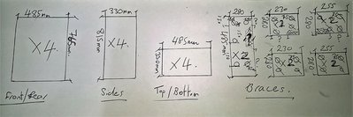
I,ve just done a cutting list for 25mm Marine Plywood.
The Dimension for the Longitudinal Brace is now on the Plan as 765mm, not the 465mm shown.
I've also changed the hole quantity, worked on the dim of 25mm from the top edge of the brace, with 50mm between the holes, this allows for 6 holes on the longititude. So approx 12 holes in this baffle.
Any corrections to offer, let me know, as I will be cutting tomorrow.
Speaker-Cabinet-Dims.jpg
as well another cutting list offered by another member in the PDF.
I,ve just done a cutting list for 25mm Marine Plywood.
The Dimension for the Longitudinal Brace is now on the Plan as 765mm, not the 465mm shown.
I've also changed the hole quantity, worked on the dim of 25mm from the top edge of the brace, with 50mm between the holes, this allows for 6 holes on the longititude. So approx 12 holes in this baffle.
Any corrections to offer, let me know, as I will be cutting tomorrow.
Speaker-Cabinet-Dims.jpg
Attachments
Last edited:
exciter design thoughts
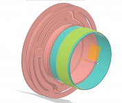
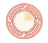
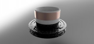
So I have been thinking about exciter design and have had a doodle in Fusion 360 to collect my thoughts. These are early ideas so all criticisms are very welcome.
The pictures attached are views of a 3D printed Carbon Fibre reinforced component that combines a spider and a thrust structure that has a much larger contact area for the panel. Sorry about the crap pink colour for the component but F360 applies the colours automatically.
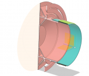
As you will see in the images below, for the spider/ suspension I am using a 2D spiral design as used by Dayton and others, which is flexible along the motor axis but stiff in all axis radial to the motor axis to support the weight of the magnets ( not shown). The only change here is the use of CF reinforced polymer which is stiff ( 10X that of a conventional polymer) but self damping. This will remove the ringing that can happen with a steel spider/suspension. The stiffness of the spider can be changed by altering the thickness of the printed part locally without adding too much weight.
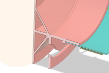
Integrated with this in the same print is the thrust structure that expands from the voice coil in three ‘branches’ to pass the energy from the exciter to the thrust plate. This is a bit controversial as we can anticipate a number of problems.
The first of these is an increase in the moving mass. I hope to offset this by the choice of material and keeping the sections as thin as possible. Currently the CF component weighs 5.2 grams. Looking at the Dayton exciter this is circa twice the thrust structure they use. This can be compensated for using larger or more powerful magnets.
The second problem is that inevitably the ‘branches’ are different lengths. This means that any impulse from the voice coil will reach the plate at different times. The inner and outer branches are longer by 2mm. However the speed of sound in CF is much higher than in air, around 5 km/sec verses 0.3315 km/sec or 15X faster so I doubt that this will be a significant issue. However the added flexibility provided by the additional length may make this more complicated as the structure may flex to a greater or lesser extent. Assuming a very worst case and that the longer branches flex all that happens is that the additional branches are redundant and the additional mass is a drag on responsiveness. However, the 3D printer I use, like most, will not print a large solid volume. Instead it prints the outer skin of the solid and replaces the bulk of the volume with a honeycomb structure that provides sufficient stiffness. This could be a good option for this design if the mass increase is not too great. I will be looking at this option.
I will make the CAD files for this component available once it is finalised. You are welcome to use them in your own experiments and adapt them if you discover some improvements. All I ask is, just like the incomparable Mr Nelson Pass, you reciprocate so we can all share any discoveries. Just like Mr Pass any commercial interest please understand the files are not available for you to exploit. I am a product designer of 30 years experience so I know exactly what to do if you attempt it.
The material is available here
3D Printer Continuous Carbon Fiber Filament Material | Markforged
Other suppliers are available with a search online.
So I have been thinking about exciter design and have had a doodle in Fusion 360 to collect my thoughts. These are early ideas so all criticisms are very welcome.
The pictures attached are views of a 3D printed Carbon Fibre reinforced component that combines a spider and a thrust structure that has a much larger contact area for the panel. Sorry about the crap pink colour for the component but F360 applies the colours automatically.
As you will see in the images below, for the spider/ suspension I am using a 2D spiral design as used by Dayton and others, which is flexible along the motor axis but stiff in all axis radial to the motor axis to support the weight of the magnets ( not shown). The only change here is the use of CF reinforced polymer which is stiff ( 10X that of a conventional polymer) but self damping. This will remove the ringing that can happen with a steel spider/suspension. The stiffness of the spider can be changed by altering the thickness of the printed part locally without adding too much weight.
Integrated with this in the same print is the thrust structure that expands from the voice coil in three ‘branches’ to pass the energy from the exciter to the thrust plate. This is a bit controversial as we can anticipate a number of problems.
The first of these is an increase in the moving mass. I hope to offset this by the choice of material and keeping the sections as thin as possible. Currently the CF component weighs 5.2 grams. Looking at the Dayton exciter this is circa twice the thrust structure they use. This can be compensated for using larger or more powerful magnets.
The second problem is that inevitably the ‘branches’ are different lengths. This means that any impulse from the voice coil will reach the plate at different times. The inner and outer branches are longer by 2mm. However the speed of sound in CF is much higher than in air, around 5 km/sec verses 0.3315 km/sec or 15X faster so I doubt that this will be a significant issue. However the added flexibility provided by the additional length may make this more complicated as the structure may flex to a greater or lesser extent. Assuming a very worst case and that the longer branches flex all that happens is that the additional branches are redundant and the additional mass is a drag on responsiveness. However, the 3D printer I use, like most, will not print a large solid volume. Instead it prints the outer skin of the solid and replaces the bulk of the volume with a honeycomb structure that provides sufficient stiffness. This could be a good option for this design if the mass increase is not too great. I will be looking at this option.
I will make the CAD files for this component available once it is finalised. You are welcome to use them in your own experiments and adapt them if you discover some improvements. All I ask is, just like the incomparable Mr Nelson Pass, you reciprocate so we can all share any discoveries. Just like Mr Pass any commercial interest please understand the files are not available for you to exploit. I am a product designer of 30 years experience so I know exactly what to do if you attempt it.
The material is available here
3D Printer Continuous Carbon Fiber Filament Material | Markforged
Other suppliers are available with a search online.
Attachments
-
 Screenshot 2019-08-11 at 13.39.44.png416.2 KB · Views: 1,165
 -
 Screenshot 2019-08-11 at 13.40.31.png232.5 KB · Views: 1,162
 -
 Screenshot 2019-08-11 at 13.41.04.png177.7 KB · Views: 1,162
 -
 Screenshot 2019-08-11 at 13.41.44.png79.3 KB · Views: 1,151
 -
 Exciter Update v11.jpg159.1 KB · Views: 267
 -
 Screenshot 2019-08-11 at 13.45.57.png162.9 KB · Views: 295
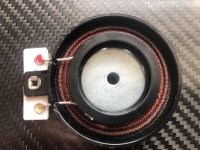
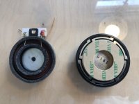
Just a quick additional note on the Tectonic exciters. I think it would be better to use the central hole to mount the exciter motor to a spine using a bolt than rely on the outer support ring. I am going to try this and will report back.
The first image below shows the Tectonic exciter without its support ring foam and adhesive. Note the inner circle is the contact area with the panel which is too small in my view. A Dayton exciter included for reference in second image.
The first image below shows the Tectonic exciter without its support ring foam and adhesive. Note the inner circle is the contact area with the panel which is too small in my view. A Dayton exciter included for reference in second image.
Attachments
Destroyer said ....
Thank you Destroyer that worked out well. I tried some 35mm thick polyester fibre mats for lining speaker cabinets and the panels sound more open.
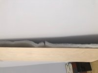
I tried the close up to the wall while I am revising the hanging method and to my surprise the sound absorption still worked pretty well, picture below.
I am now back at close to Varaize levels of sound quality with just the sound stage more 'compact' than the big space I have there but still very enjoyable.
I will still follow up on the different panel materials to feed back on the last of the variables.
Summary to date
- Matching the right exciter to the right panel is key.
- The amount of energy put out by exciters varies- big panels need strong exciters or multiple smaller exciters to work well.
- Sound absorption on the rear panel does make the rear room volume 'bigger' and works well if you have to mount panels close to the wall
-if you have the room, a lot of space behind the panels creates a huge soundstage
- You need a subwoofer- DML's don't do slam but will reach down circa 80-100hz happily.
- You can eq a panel to give a flat response effectively
- DML's sound like nothing else for the money with outstanding VFM and WAF.
My wife thinks these speakers are FUN!!! That has never happened before.
.... along with other good stuffAbsorption material behind it will make it "think" that it's in a larger space. Basically you stop reflections that reinforce the movement and make it damped better - less sloppy.
Thank you Destroyer that worked out well. I tried some 35mm thick polyester fibre mats for lining speaker cabinets and the panels sound more open.
I tried the close up to the wall while I am revising the hanging method and to my surprise the sound absorption still worked pretty well, picture below.
I am now back at close to Varaize levels of sound quality with just the sound stage more 'compact' than the big space I have there but still very enjoyable.
I will still follow up on the different panel materials to feed back on the last of the variables.
Summary to date
- Matching the right exciter to the right panel is key.
- The amount of energy put out by exciters varies- big panels need strong exciters or multiple smaller exciters to work well.
- Sound absorption on the rear panel does make the rear room volume 'bigger' and works well if you have to mount panels close to the wall
-if you have the room, a lot of space behind the panels creates a huge soundstage
- You need a subwoofer- DML's don't do slam but will reach down circa 80-100hz happily.
- You can eq a panel to give a flat response effectively
- DML's sound like nothing else for the money with outstanding VFM and WAF.
My wife thinks these speakers are FUN!!! That has never happened before.
Attachments

Curious about these Gizmos.
It does occur tho that while the 'piston' acts on the Whatever it's stuck to diaphragm What? deals with the opposite reaction of the motor assly ?
Some glued onto the diaphragm bodge ?
Logic suggests this as seriously inefficient and likely wave cancelling.
This Not a real life issue with these.. then ?
Would not a motor mount frame, totally separate from the Diaphragm be an alternate approach?
Say a rigid metal radial mount arrangement using Flexi surround type point supports for the diaphragm.
In effect building a 'large' flat speaker be a worth trying path?
The panel has finite mass, and thus, inertia. The inertia resists the sudden motion (pressure) of the transducer and thus flexes. The transducer also has mass and resists its own motion in opposite direction. It is not pistonic motion, but the transducer effects multiple modes of complex vibration - the panel oscillates in and out over many spots like a high order drum membrane - hence the name “distributed mode”. The sound is actually closer to an omni directional speaker than a dipole or an OB.
This can be seen in videos where the host put particles on the membrane and vibrated it to show modes.
This can be seen in videos where the host put particles on the membrane and vibrated it to show modes.
Last edited:
Hi Bare,
These weird beasts operate in a very different way to 'normal' dynamic speakers. Like xrk971 says they are not pistonic in operation. Sound is produced by exploiting resonant modes leading to a chaotic state in the panel, which sounds like a recipe for colouration, but it isn't. Sound propagates across the panels in transverse waves rather than the expected front to back motion cones and domes exhibit. The sound from the back is in phase with the sound from the front unlike an OB or ESL.
Operationally as xrk971 notes there is sufficient mass in the panels and the exciter mass to provide reaction mass.
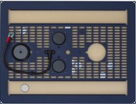
Having said that some manufacturers of professional systems do provide support to the exciters. This may improve the performance, some on here swear by it, and it's on my list to try. There is a picture below of the back of a professional system for ideas.In the picture you can see three exciters mounted on a metal frame with a hole for a fourth. You can also see some pucks that are used by this manufacturer to tune the panels. Lots to explore and learn with DML's and they can sound unbelievably good.
Burnt
These weird beasts operate in a very different way to 'normal' dynamic speakers. Like xrk971 says they are not pistonic in operation. Sound is produced by exploiting resonant modes leading to a chaotic state in the panel, which sounds like a recipe for colouration, but it isn't. Sound propagates across the panels in transverse waves rather than the expected front to back motion cones and domes exhibit. The sound from the back is in phase with the sound from the front unlike an OB or ESL.
Operationally as xrk971 notes there is sufficient mass in the panels and the exciter mass to provide reaction mass.
Having said that some manufacturers of professional systems do provide support to the exciters. This may improve the performance, some on here swear by it, and it's on my list to try. There is a picture below of the back of a professional system for ideas.In the picture you can see three exciters mounted on a metal frame with a hole for a fourth. You can also see some pucks that are used by this manufacturer to tune the panels. Lots to explore and learn with DML's and they can sound unbelievably good.
Burnt
Attachments
Last edited:

Just a quick additional note on the Tectonic exciters. I think it would be better to use the central hole to mount the exciter motor to a spine using a bolt than rely on the outer support ring. I am going to try this and will report back.
The first image below shows the Tectonic exciter without its support ring foam and adhesive. Note the inner circle is the contact area with the panel which is too small in my view. A Dayton exciter included for reference in second image.
With the Tectonics, maybe extend the inner ring to gain some clearance from the outer, then could possibly use some form of damping on the outer ring as required. Start with little foam squares?
Ok XK /Burnt thanks..Hi Bare,
These weird beasts operate in a very different way to 'normal' dynamic speakers.
Operationally as xrk971 notes there is sufficient mass in the panels and the exciter mass to provide reaction mass.
Having said that some manufacturers of professional systems do provide support to the exciters. This may improve the performance, some on here swear by it, and it's on my list to try. There is a picture below of the back of a professional system for ideas.In the picture you can see three exciters mounted on a metal frame with a hole for a fourth. You can also see some pucks that are used by this manufacturer to tune the panels. Lots to explore and learn with DML's and they can sound unbelievably good.
Burnt
I was thinking on the Motor/magnet assly bouncing about largely uncontrolled ..
Clearly the Diaphragm does have inertia.
Likely far More effective mass than the wee motor assembly manages.
Presumably allowing it to bounce about reactively.. wasting /interfering with signal energies.
Regardless of how small the travel.. There IS pistonic movement. from the voice coil.
Also the typical attachment of the Motor to the Diaphragm.. with a foamy taped on spider affair... Must interfere in some degree with the wave propagation.
Mounting reads as a pretty good damping device... likely affecting a fair bit of the signal wave in process.. also not finding a plausible explanation
of the motors imparted reverse/cancelling.. wave due to motor movements (however slight)
Yeah..
I've watched the Utubes of the ernest old guy with the Comb over.
Curious entertainment there.
Bare you have some reading to do. Start here https://www.tectonicaudiolabs.com/wp-content/uploads/2018/10/DML-Theory-and-Practice.pdf
Hi Jerms,
You are thinking just like the Tectonics designer. The central ring is raised and the outer ring had a foam ring that acted like a damper/support that isolated the mass of the exciter from the panel.
You are thinking just like the Tectonics designer. The central ring is raised and the outer ring had a foam ring that acted like a damper/support that isolated the mass of the exciter from the panel.
Bare you have some reading to do. Start here https://www.tectonicaudiolabs.com/wp-content/uploads/2018/10/DML-Theory-and-Practice.pdf
Bare
This is a better introduction if you don't want the maths
http://www.daytonaudio.com/media/re...-and-using-dayton-audio-exciters-revised2.pdf
Burnt
- Home
- Loudspeakers
- Full Range
- A Study of DMLs as a Full Range Speaker