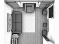
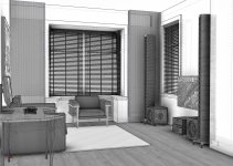
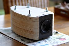
Thanks! That's what it looks like after a bit of remodeling over here. Except that the arrays and subs are still in storage 😀.
I'll add another set in black and white, showing hidden lines...
I'll add another set in black and white, showing hidden lines...
Attachments

Last edited:
Attachments
Last edited:
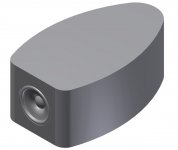
Yes that is basically what is needed 🙂@fluid, do we need something like this?
Still need to add a top/bottom to the first one for it to represent my test cabinet.
I can send it to you trough mail, and can easily adjust it to represent your lines as well.
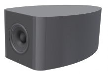
The images above look good. For confirmation purposes it would be good to have one without the roundover in front of the driver too, as that effectively makes the cone deeper and will change the response.
email me them as step files and I will look to see what I can do to mesh them 🙂
My test box is flush, so that was what I've copied, plus a version with round-over just to see what changes if it all works out. Next a mini array version of with 3 drivers flush and 3 with round-over. If all goes well you'll be receiving 4 STEP files right now 😉.
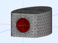
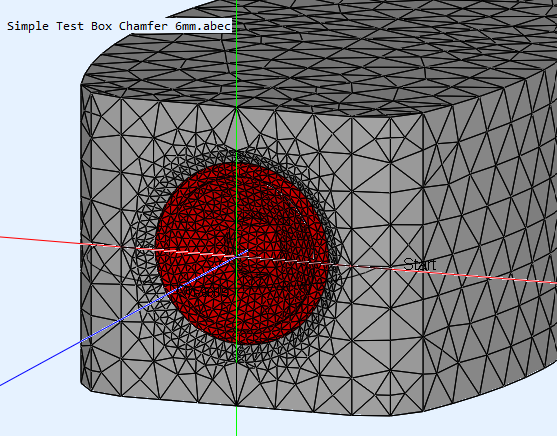
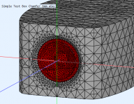
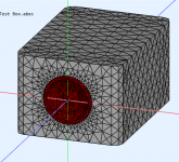
I was able to simulate the flush test box in ABEC with a simplified model of the TC9 based on wesayso's CAD files.
This is the mesh

Results attached below, without a LE script for the driver, seems reasonable. Refinements can be made such as using different weights to drive the cone and surround and the LE script but this seems to show the basic s are working.
This is the mesh
Results attached below, without a LE script for the driver, seems reasonable. Refinements can be made such as using different weights to drive the cone and surround and the LE script but this seems to show the basic s are working.
Attachments

Very cool fluid, I'm hoping the version with round-over in front of the cone works too..
If we got both of those, it would probably make sense to look at the partial array featuring 3 drivers, while driving the bottom one (or center) to see what it does vertically.
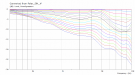
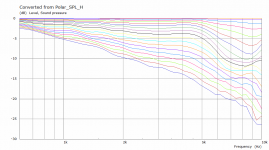
Here's the horizontals that nc535 came up with (Vituixcad) which formed the base for our simulations:
If we got both of those, it would probably make sense to look at the partial array featuring 3 drivers, while driving the bottom one (or center) to see what it does vertically.
Here's the horizontals that nc535 came up with (Vituixcad) which formed the base for our simulations:
Attachments
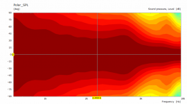
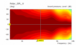
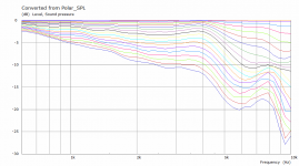
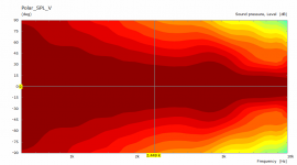
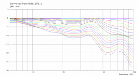
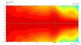
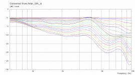
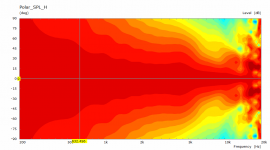
Here is the Vertical Polars and normalised curves, not too bad either, more baffle and no roundover on the edge creates a different pattern when other drivers are added that will change things.
Attachments
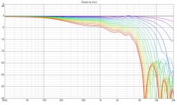
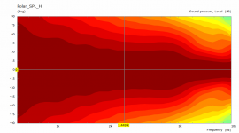
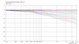
This is the simulation for adding a 6mm chamfer in front of the driver. The directivity is quite a bit better particularly below 5K in the Horizontal, good choice 🙂
Attachments
It might be worth it! 🙂
Thanks for doing these, fluid! Very informative. I did expect to see some of it, due to finding measurements of a TC9 in both flush mount and back mounted enclosure, before I made my decision to go for it. Sadly, that thread remained, the pictures were lost through the years. Not even the "wayback" engine could find those again.
Thanks for doing these, fluid! Very informative. I did expect to see some of it, due to finding measurements of a TC9 in both flush mount and back mounted enclosure, before I made my decision to go for it. Sadly, that thread remained, the pictures were lost through the years. Not even the "wayback" engine could find those again.
Wow, the tools now available to the DIY community are simply incredible.
Thanks for sharing, guys.
Thanks for sharing, guys.
This is the simulation for adding a 6mm chamfer in front of the driver. The directivity is quite a bit better particularly below 5K in the Horizontal, good choice 🙂
Does this imply a 12mm "front" with a 6mm chamfer or is the front also 6mm thick?
//
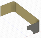
No thickness to the enclosure is needed or implied from the model this is what the one I'm running now looks like. It is a surface which encloses a volume, unless you want to model the inside it doesn't matter.
The chamfer is 6mm inset into the front surface.

The chamfer is 6mm inset into the front surface.
Attachments
are we going all the way to a line array waveguide? It would be interesting to see what it takes to control H directivity down to 1 or 2 khz, ... along with the vanes
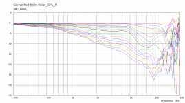
Maybe 😉 Here is my own enclosure modelled with the same vertical size as wesayso's. Disappointing enough to seriously consider V2 based on optimized directivity.are we going all the way to a line array waveguide?
I've always had trouble getting 3 to 4K right and listening directly on axis has been better. I think these plots explain why 🙄
Attachments

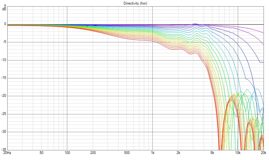
wesayso asked if I could change the range to go out to 20K. Unfortunately you can see from this that above 12K or so the mesh is not fine enough (among other issues) to generate reliable data and you get garbage. The driver is already at 4mm mesh, it could be finer for the single driver simulations but that would preclude going to a full line because the elements would get out of control. What might be worth looking at is a phase shield to try and do something in the 5k to 10K range where it is not as well controlled as below.
Attachments
- Home
- Loudspeakers
- Full Range
- The making of: The Two Towers (a 25 driver Full Range line array)