Wow, the tools now available to the DIY community are simply incredible.
Thanks for sharing, guys.
AMAZING!
Look at you guys: this is open source research and development.

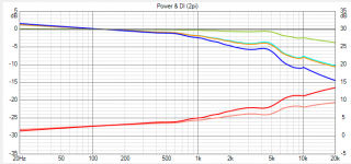
With wesayso's baffle layout and a 6mm chamfer if you limit the range to 5K and go down to 200Hz I would say this is a pretty good waveguide with reasonable control at 1K
It almost makes me look like a wise man 🙂.
I took inspiration form koldby (for the backmounting idea, of which I did find evidence that pointed at good results), an old thread from Patrick Bateman on using round shapes, B&W's teardrop obviously and Humble Homemade Hifi's Mezzo Galactica's.
The above combined, together with the famous Olsen graphs,

was inspiration enough to create my "egg shaped" enclosure. Trying to come up with fluent lines, which I tested in Hornresp's ripple tank, making it an 'almost inverted' waveguide shape.
It wasn't until after I had build them that I found out about the Magico Mini. A shape they have abandoned for quite some time, but their latest work is moving towards round shapes again.
Attachments

Last edited:
Maybe 😉 Here is my own enclosure modelled with the same vertical size as wesayso's. Disappointing enough to seriously consider V2 based on optimized directivity.
I've always had trouble getting 3 to 4K right and listening directly on axis has been better. I think these plots explain why 🙄
Obviously, your going to test this enclosure shape with a chamfer/round-over in front of the driver, right? 🙂
wesayso asked if I could change the range to go out to 20K. Unfortunately you can see from this that above 12K or so the mesh is not fine enough (among other issues) to generate reliable data and you get garbage. The driver is already at 4mm mesh, it could be finer for the single driver simulations but that would preclude going to a full line because the elements would get out of control. What might be worth looking at is a phase shield to try and do something in the 5k to 10K range where it is not as well controlled as below.
Not completely unexpected... it would be fun to be able to test the generated curves in Vituixcad though.
I'll send you the Vituix data to 10K, Vituix is pretty good at making up what doesn't exist 🙂 It will be interesting to see if this affects much in your overall Vituix model. As it is normalized it is already pre EQ'd. Do you want it normalized to 10 deg off axis?
No, on axis would be fine...
Great results by the way, to bad the run up to 20 KHz didn't work.
Great results by the way, to bad the run up to 20 KHz didn't work.
sharing thoughts ....does the region above 10 k really matter to anyone's perception other then subjectively perceived "airiness" (if that is phonetically correct), as someone who has been victim to the struggle over SPL VS "QUALITY" for years has wondered and witnessed the "line array" pheneom in live sound has wondered? (oops that may be scotch influenced...but i think you may get my gist..)
I wouldn't disagree with you, even when sober 🙂.
For my personal goals I want the bandwidth that contains the most important parts in music to be the best representative I can make it, I'll settle for a somewhat less stellar top end, one could most probably add upper 'ambience' with tweeters if needed?
On axis and over the listening area there will still be valid "signal" available. Not quite as good as some other types of speakers, but I don't see it as one of the most important parts having heard domes on the top end of studio speakers, that created something I've never heard in un-amplified live performances. Boom and tizz is popular though, just not really my thing. I want to be "fooled" with a believable atmosphere. Some nice and controlled boom is a nice atmosphere creator though, I'll have to say that. Just not the one note wonder... But I don't mind being able to feel as well as hear the music. for me, that is part of the experience.
Last edited:
ok thanks, have one on me (we'll tally and settle the tab later)
"For my personal goals I want the bandwidth that contains the most important parts in music to be the best representative I can make it" (sorry with the new rules of "quote" i can't do a proper quote thingy...) i whole heartedly agree i spent years listening to multiway PA systems listening to x-over's in the mid range and wished for better
"For my personal goals I want the bandwidth that contains the most important parts in music to be the best representative I can make it" (sorry with the new rules of "quote" i can't do a proper quote thingy...) i whole heartedly agree i spent years listening to multiway PA systems listening to x-over's in the mid range and wished for better
Last edited:
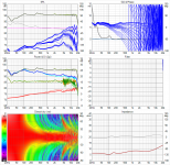
Just a quick try with the ABEC generated directivity:

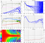
Compared to the original simulation:

Not much differences, only minor. In fact, the FR curves are a little better, but as the drivers have a wider pattern, the floor/ceiling splash is a bit more intense too. Not much, but it's there. The pattern is more even with the ABEC directivity files. Off axis it is more controlled than our first data set assumed.
The idea behind the ABEC simulations was to find a way to limit the vertical pattern for each driver in some way, which would make the lobes less intense. We still have to come up with that part. But fluid does have other things he needs to attend to first 😉. I'm in no hurry and could probably learn how to do the ABEC simulations so he won't have to 🙂.
Compared to the original simulation:
Not much differences, only minor. In fact, the FR curves are a little better, but as the drivers have a wider pattern, the floor/ceiling splash is a bit more intense too. Not much, but it's there. The pattern is more even with the ABEC directivity files. Off axis it is more controlled than our first data set assumed.
The idea behind the ABEC simulations was to find a way to limit the vertical pattern for each driver in some way, which would make the lobes less intense. We still have to come up with that part. But fluid does have other things he needs to attend to first 😉. I'm in no hurry and could probably learn how to do the ABEC simulations so he won't have to 🙂.
Attachments
Last edited:
I'm glad there is no need to adjust your filter boards 🙂Not much differences, only minor.
You could easily learn to do it and I will make a thread to show how to do it. There is effort involved but it is not hard. Your CAD skills give you a leg up in making meshes.I'm in no hurry and could probably learn how to do the ABEC simulations so he won't have to 🙂.
Today I moved all the things off the table I made for my CNC, so now I am back at the same point I was a year ago 😉
I'm glad there is no need to adjust your filter boards 🙂
Yes, I was real happy to see that too!
You could easily learn to do it and I will make a thread to show how to do it. There is effort involved but it is not hard. Your CAD skills give you a leg up in making meshes.
To think I was even reluctant to learn Vituixcad...
Even if there isn't a way to easily improve what I've got, I like that I was able to finally see that my first choices were in the ball park. I'm glad to see confirmation of the shape I chose, which was meant to limit the effects of diffraction.
Today I moved all the things off the table I made for my CNC, so now I am back at the same point I was a year ago 😉
But you did gain a lot of wisdom in the mean time, right? 🙂
At least that's how I look at it... every little step counts...
Knowing what it is you want isn't easy in this game...
The new plots showed even more ideal and wider horizontal pattern control, but wider vertically too, which does mean stronger floor/ceiling splash.
If only that could be cured with simple baffle geometry. I sure haven't figured that one out yet.
If only that could be cured with simple baffle geometry. I sure haven't figured that one out yet.
I do have ideas about what I want to try, probably not a surprise 😀.
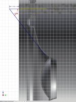
I figured why not try something like a E-JMLC, but folded back. As I've shown the shape of my current waveguide in a cross section (folded back), pretend this shape to be part of it:

But there won't be room (between drivers) for a rolled lip, so it becomes sort of a vane in-between the drivers, if one folds it all the way back.
The horizontal vs vertical plots on this model do show the behavior I want to exaggerate. See: E-JMLC-1000 – Horns by Auto-Tech
See how the vertical drop is way faster than the horizontal is? Ideally I'd want that drop happen at ~3 KHz (or a bit sooner) to limit the energy going off axis in the vertical direction. Any drop vs what we have now is pure profit.
As we have seen, even a little horn (the 6mm back mount) has an influence. The cone in this situation is part of the waveguide, that chamfer is sort of an extension of that shape. Now all I need to create is a similar extension between the drivers that mimics the E-JMLC pattern control.
Does it make sense? 😱
😱
I figured why not try something like a E-JMLC, but folded back. As I've shown the shape of my current waveguide in a cross section (folded back), pretend this shape to be part of it:
But there won't be room (between drivers) for a rolled lip, so it becomes sort of a vane in-between the drivers, if one folds it all the way back.
The horizontal vs vertical plots on this model do show the behavior I want to exaggerate. See: E-JMLC-1000 – Horns by Auto-Tech
See how the vertical drop is way faster than the horizontal is? Ideally I'd want that drop happen at ~3 KHz (or a bit sooner) to limit the energy going off axis in the vertical direction. Any drop vs what we have now is pure profit.
As we have seen, even a little horn (the 6mm back mount) has an influence. The cone in this situation is part of the waveguide, that chamfer is sort of an extension of that shape. Now all I need to create is a similar extension between the drivers that mimics the E-JMLC pattern control.
Does it make sense?
😱Attachments
Last edited:
I can't visualize it, maybe you can draw it?I figured why not try something like a E-JMLC, but folded back. As I've shown the shape of my current waveguide in a cross section (folded back), pretend this shape to be part of it:
I worry that anything that might work will either not fit on your existing baffle or be as ugly as a hatful of "insert anything ugly here" 😉
Well, don't think of that horn I posted too much, I really hove it wouldn't have to look like that 😀.
I am trying to come up with something, looking at the cone of the TC9, and "pretending" to know where the frequencies of interest are coming from.
If something small can work, it could be OK. But I'm not willing to put large vanes on the baffle, even if it might work. I don't want to build reflectors, but guides.
Basically, the cross shape of the enclosure and especially back mount radius acts as a guide, what goes in the vertical direction is as wide as what goes to the sides. That should be limited somewhat vertically, drop off a little sooner, which the E-JMLC seems to do. So if the guide is larger (as in protruding from the baffle, making it more narrow) in vertical direction, it may have similar effects?
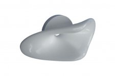
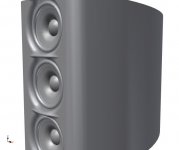
Let me put up a sample:

Another 6mm added, steeper curve than the roundover on the sides, still have to cut it and roundover re-applied, half round shape if seen from the top.
I am trying to come up with something, looking at the cone of the TC9, and "pretending" to know where the frequencies of interest are coming from.
If something small can work, it could be OK. But I'm not willing to put large vanes on the baffle, even if it might work. I don't want to build reflectors, but guides.
Basically, the cross shape of the enclosure and especially back mount radius acts as a guide, what goes in the vertical direction is as wide as what goes to the sides. That should be limited somewhat vertically, drop off a little sooner, which the E-JMLC seems to do. So if the guide is larger (as in protruding from the baffle, making it more narrow) in vertical direction, it may have similar effects?
Let me put up a sample:
Another 6mm added, steeper curve than the roundover on the sides, still have to cut it and roundover re-applied, half round shape if seen from the top.
Attachments
Last edited:
I can't call it pretty yet... 🙄
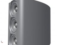
Done another way, not much prettier...
Attachments
Last edited:
Another day, another 'fresh' view? Option 2 looks way better to me. It could be made as a separate element and not be totally off. That is, if it brings any use with it.
- Home
- Loudspeakers
- Full Range
- The making of: The Two Towers (a 25 driver Full Range line array)