Hanning nonlinear-compensation/getHarmonics.m at master * pavhofman/nonlinear-compensation * GitHub
FFT samplerate samples long, i.e. precision 1Hz. Works reliably.
FFT samplerate samples long, i.e. precision 1Hz. Works reliably.
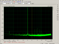
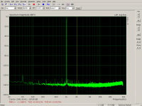
Just an example of joint-device compensation (on recording side, contributions not split to DAC/ADC) of 1021Hz/96kHz at full level -1dB. The cursor is placed at second harmonic 2042Hz to show the measured level.
The soundcard noise < 2kHz is very likely caused by a fan near the card in the PC case. For final application a soundcard must be located outside the PC case, preferably hooked to a notebook e.g. via expresscard -> PCI-e adapter ( V8 EXP GDC Laptop External Independent Video Card Dock Mini PCI-E for Beast | eBay on the way for testing) running on batteries to avoid any ground loops.
Newly implemented:
* continuous tracking of incoming signal with FFT (1 second of continuously update samples, 1Hz resolution, the FFTW library used by octave is very fast)
* ignoring short-time glitches of FFT results when the incoming signal changes frequency/arta changes FFT length etc.
* automated selection of calibration profiles -> compensation or passing unchanged samples if no supported input signal fundamentals are detected or corresponding calibration profile unavailable .
* compensation decision is handled for each channel separately/individually. This change will support the planned virtual balanced mode where one channel may hold the main signal (compensating the fundamentals), while the other channel may hold only the common-mode noise to be subtracted from the first channel (no fundamentals, only passing samples to the subtraction=balancing stage)
* calibration profiles are stored for each channel separately.
Splitting calibration files for each channel. Removing global freqs. … * pavhofman/nonlinear-compensation@c8f6e61 * GitHub
Next crucial step is continuous interpolation of distortion params between pre-calibrated levels to fit the current incoming signal level. Compensation is currently very sensitive to changing the incoming level from the calibration level, the hope is interpolation of amplitude/phase between closely calibrated levels will fit reality better than dumb distortion amplitude adjustment by currentAmpl/calibratedAmpl.
If the presumed effect of interpolation proves to work in practice, basically all the proof-of-concept theory->practice catches should be resolved and further development would be "only" coding features/usability.
Attachments
Last edited:
Interpolation for calibrated levels is basically finished. It seems to behave OK, 1 dB calibration step will be probably enough (of course depending on the soundcard).
Distortion peaks are averaged across several 200ms cycles to avoid storing externalities.
The feature took quite a lot of changes, storing multiple levels into calfiles, optimizing the interpolation code to minimize CPU load, handling missing values for some level/distortion frequency combinations, handling extrapolation for levels outside the calibrated range.
The splitting code is not modified to handle the new format of calibration files yet, I will fix it after the format becomes stable.
Measuring peaks with 1Hz FFT bin + compensating 40 distortion freqs of dual-tone 4 + 4.5kHz/48kHz takes under 70ms in every 200ms cycle on my older 2.4GHz Xeon core - quite safe margin for avoiding buffer underruns.
I guess time to start working on the GUI - probably some chart depicting calibrated levels vs. current level will be the first. This requires implementing duplex communication between octave processes - not decided about technology yet, probably plain files for start.
Should anyone be interested in testing the joint-device mode in linux + wine + Arta, it would help towards checking real usability/repeatability of the project. I would write the installation/operation readme in case of interest.
The split compensation deals with both sides.
DAC - cleaner source of single/dual frequencies.
ADC - less distorting AD conversion at single/dual frequencies
(splitting joint-sides for dual freqs is not implemented yet)
Both sides can have analog buffers or gain stages added, but these must be part of the calibration loop and their gain cannot be changed after calibration.
Application
* low-distortion harmonic generator of arbitrary frequency
* measuring low DUT harmonic distortions with signal synchronous to ADC clock (typically the same soundcard)
"Clean" means "to the extent allowed by the technology"")
DAC - cleaner source of single/dual frequencies.
ADC - less distorting AD conversion at single/dual frequencies
(splitting joint-sides for dual freqs is not implemented yet)
Both sides can have analog buffers or gain stages added, but these must be part of the calibration loop and their gain cannot be changed after calibration.
Application
* low-distortion harmonic generator of arbitrary frequency
* measuring low DUT harmonic distortions with signal synchronous to ADC clock (typically the same soundcard)
"Clean" means "to the extent allowed by the technology"
Both sides can have analog buffers or gain stages added, but these must be part of the calibration loop and their gain cannot be changed after calibration.
To clarify the fixed gain - active components change their distortion profile at various gains. A passive voltage divider with close-to-zero distortion can be set at any level after calibration.
ZeroMQ messaging has proven quite easy to use, providing reliable transfer of complete octave struct variables between running processes. The playback and capture processes are sending their current status to the main controller now, any of the processes can stop running without blocking the other two, communication is resumed automatically after joining-in.
Time to start preparing some usable GUI, the worst part of the project for a backend person
So far all the used/required packages are part of the prebuilt octave installer for MS Windows, hopefully will run OK there.
Time to start preparing some usable GUI, the worst part of the project for a backend person
So far all the used/required packages are part of the prebuilt octave installer for MS Windows, hopefully will run OK there.
FFT is used for two purposes:
1) Calibration - measuring fundamentals and distortions to be stored to calibration files. The calibration is stored only if FFT finds one or two bins with fundamentals. Zero => skip, more than two => skip. Each bin is 1Hz wide, the windowing function has behaved OK in all the tests so far. Calibration signal can be generated directly by the playback side, if needed.
Measured distortions are averaged over several cycles to store representative values.
2) Continuous analysis of the signal from DUT. In this case only fundamentals are used, distortions carry the to-be-measured characteristics of the DUT. Again, only one or two found fundamentals + availability of corresponding calibration files result in compensation. Otherwise the samples are passed without any change (besides channel-gain equalization for virtual input balancing).
Analysed fundamental frequencies must hold same for two subsequent cycles (400ms) for the compensation to kick in.
Certainly numerous corner cases will be identified and fixed when the system gets tested in more installations and measurements. Do you want to revive your tester background?
Here is a question the just surfaced where this technique may show real answers:
The ESS DAC's seems to have a tunable distortion correction feature. My question was whether the correction would hold in the presence of other signals or only help in distortion measurements. So if another unrelated tone is added (at -40 dB even) what happens to the effectiveness of the distortion correction? Adding it either to the digital source or as an analog signal in mid chain would answer a lot of questions.
I do need to set up the digital compensation but have been slammed for time for months now.
I do need to set up the digital compensation but have been slammed for time...
I have used them before. I have some Arduino code to read and write the double precision signed int types over I2C, if that might be of any interest.
The ESS DAC's seems to have a tunable distortion correction feature.
IMO the ESS distortion correction is changing some parameters of the DAC in order to reduce distortion of that particular piece/implementation circuit. If there was a universal optimal value, why would ESS not hard-code this into their DACs? I do not have any experience/info with that but I would assume the value is experimentally obtained by measuring the distortion for the given piece or circuits around.
My question was whether the correction would hold in the presence of other signals or only help in distortion measurements. So if another unrelated tone is added (at -40 dB even) what happens to the effectiveness of the distortion correction?
I have not tested these scenarios yet. The analysis section keeps monitoring the incoming signal and determines one or two fundamental freqs. If a change in fundamentals is detected, the code looks for a pre-stored calibration profile and applies it. The current version just passes samples when no appropriate profile is found or more than two fundamentals are found.
It is possible to implement some compensation mode hints where you could say "compensate at 1kHz" and the code will ignore all the other fundamentals. That way it would compensate only harmonics related to 1kHz, even if there were other frequencies mixed in. I have not tested the results.
The detected fundamentals are currently those within -20dB of the strongest frequency. A signal at -40dB is ignored by the analysis detector as it is likely a product of the DUT. Of course any distortions arising from this signal will not be compensated but these would be tiny.
What are you exactly trying to achieve?
Last edited:
My underlying question is whether the distortion compensation still works when some other disturber is present. Essentially wither its useful on music or only relevant for stationary signals. My thought was that the digital compensation may be a model to check with. I may have another way to test this as well.
It is intended to work on music, not just stationary signals. It seems to be very simple thing that alters the channel signal level transfer function (e.g. output-volts/input-volts) from a straight line of some slope (gain), to a slightly curved line where gain is a function of instantaneous signal level.
Last edited:
Correcting a non-linear transfer is one thing, the other is to know what the error is. I doubt that ESS is doing an actual real time 'measurement' of the non-linearity like phofman does, so they must have an a priory idea what the error is. In that case they might as well hard-code the correction, but making it selectable may have a marketing advantage.
Jan
Jan
it is adjustable, not just on/off. They use 16-bit signed int registers with the midpoint, zero, being no correction. They suggest the registers could be used to compensate for non-linearities in the external analog electronics. I think if you want to know more, you will have to get a data sheet and or talk to them.
Last edited:
Here is a question the just surfaced where this technique may show real answers:
The ESS DAC's seems to have a tunable distortion correction feature. My question was whether the correction would hold in the presence of other signals or only help in distortion measurements. So if another unrelated tone is added (at -40 dB even) what happens to the effectiveness of the distortion correction? Adding it either to the digital source or as an analog signal in mid chain would answer a lot of questions.
I do need to set up the digital compensation but have been slammed for time for months now.
This was what I was fishing for
- but I concluded that it was probably not possible. But maybe then...//
- Home
- Design & Build
- Equipment & Tools
- Digital Distortion Compensation for Measurement Setup