That's a very nice idea! Once you are doing what you are doing, you could probably take on frequency response compensation as well. Probably only needs to be done once/rarely. But needs to be done at each atten. setting.
How do you do that with the distortion compensation, does that need to be done for each atten. setting?
Jan
How do you do that with the distortion compensation, does that need to be done for each atten. setting?
Jan
Once you are doing what you are doing, you could probably take on frequency response compensation as well.
I have not studied the problem yet to be able to tell the actual compensation procedure. There would be some filter with properly identified coeffs. I can only measure against something - either previous measurement on the same channel or simultaneous measurement on the second channel. I could probably design a filter which for the given attenuator setting will keep the amplitude of frequency response constant while phase equal (more or less) to the other channel which goes directly without the attenuator. If the other nonattenuated channel turns the phase, I have no way to find out.
It would always compensate frequency response of the overall chain: DAC -> divider -> ADC.
Probably only needs to be done once/rarely.
Yes, the divider capacitance/overall frequency response will not change a lot.
But needs to be done at each atten. setting.
The attenuator will have 512 steps - the high resolution is needed for calibration. But only a few steps will be offered/used during measuring (6dB step?). The frequency response calibration will have to be done for these only.
The good thing is this compensation does not have to be implemented now, it can be added later on. Since it is only in software, it will not require any adapter hardware changes. I like it that way 🙂
Actually the duplex realtime DSP processing layer between the soundcard and the measurement software offers great development options for the future. I believe that we have not envisioned many useful features/functions yet, all implementable by extending the software only.
Last edited:
How do you do that with the distortion compensation, does that need to be done for each atten. setting?
The attenuator itself introduces no distortion. It is the signal level throughout the ADC (and DAC) circuitry which defines the distortion. The planned calibration of the ADC side (using already cleaned/compensated DAC side by previous split-side calibration/calculation) would be following:
1) the incoming measured signal from DUT has some known level (constantly being measured)
2) the user requests the calibration (icon or menu command)
3) the measurement adapter disconnects DUT inputs/outputs, feeds the current DAC output (already clean) into the divider -> ADC. Adjusts the divider to get the closest possible signal level as was during the measurement. ADC-side calibration runs at this exact level.
4) the divider is instructed to raise/lower the signal by 0.1dB in each direction. At each level the ADC-side calibration runs. This provides data for distortion interpolation of the actual level. Depending on level stability of the measured signal, more points more distant from the exact level can be calibrated. The goal is to make sure the interpolation does not turn to extrapolation which is inherently more guessing = less precise.
5) The DUT is again connected. Since it is fed with the same DAC signal as before, it should output approx. same signal into ADC - but compensated at that particular level now (with safe interpolated margin for input DUT amplitude variation).
Last edited:
Adjusts the divider to get the closest possible signal level as was during the measurement. ADC-side calibration runs at this exact level.
Yes that'll do it. I think you have something going that potentially can be a game changer. Be sure it is safe with you ;-)
Jan
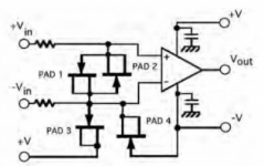
overvoltage protection with low-leakage clamp diodes to +/-3V
This is a minor point, but low capacitance is more important than low leakage (in practice they go hand in hand). The capacitance presented by the steering diode will be very sensitive to voltage and for low-distortion you need to remove as much voltage-dependent capacitance everywhere you can (use C0G caps, thin film resistors, etc). A BAV199 is around 2 pF. USB3 TVS protection diodes get even better (0.5 pF), but you don't get the range of voltages to pick from. The 2 pF is a reasonable place to be.
Also, a lot of modern opamps have built-in ESD steering diodes from the inputs to the rails, and if you just parallel those with an external over-voltage steering diode, you run the risk of the opamp IV transfer function being lower than your external IV function (eg opamp diode Vf is 0.30V and external Vf is 0.35), and the first over voltage event results in the opamp taking far more than you expected--they can only take 10 mA absolute max. So, rather than dump to a rail, dump to a TVS set several volts below the rail. That way, the opamp will never see any input excursion beyond the rail.
These are important points. Also be aware that clamp diodes to the rails, when activated, dump into the power supply. Most power supplies cannot sink current so you run the risk that you overvoltage the supply!
Jan
Jan
Thanks for the important points.
I have used BAV199 in my previous project Balanced Amp Outputs Measurement Adapter and it is my candidate. Also, I do not want to dump the diodes to rails, that would be too large a signal for the soundcard input. My original plan was +/-3V using simple zener diodes from the rails. Serial resistors before the clamping diodes should limit the dumping current sufficiently even for high overvoltage.
Another set of clamping diodes behind the opamp to protect the soundcard input for 10x mode.
This is exactly the way I did it in the autoranger. For low noise, while still having enough current limiting, I used a series R of 3.9k.
But I found that it is hard to completely remove the effect of the diodes from the distortion generation. Your BAV's may be better, I used FDH300's for their extremely low leakage.
I'll get me some of those BAVs with my next Mouser order.
Jan
But I found that it is hard to completely remove the effect of the diodes from the distortion generation. Your BAV's may be better, I used FDH300's for their extremely low leakage.
I'll get me some of those BAVs with my next Mouser order.
Jan
Thanks for the confirmation. Actually I spent quite some time looking for a diode with minimum leakage and BAV199 turned out a reasonable compromise.
Another option is JFET as a diode - typically much better leakage than a diode but rather low max. voltage (40V).
JFET as blocking diode? - Electrical Engineering Stack Exchange
http://www.ti.com/lit/an/sboa058/sboa058.pdf
Details
https://doc.xdevs.com/doc/_Metrology/Print Ver. - Current_Sources_and_V _Refs.pdf chapter 6.6 page 180 , figure 6.30B.
The recommended JFET MMBF4117 https://www.tme.eu/cz/Document/e64ad415c5ade62bf707a72c1988bad6/MMBF4117.pdf has max reverse voltage 40V, max. Igf 50mA (serial 1k should be OK), leakage current for 3V about 200fA.
Attachments
Yes, well known, I got some 4117's from LIS but didn't get around yet to try them. Also quite more expensive than the diodes.
I can send you a couple if you want to try them.
Jan
I can send you a couple if you want to try them.
Jan
Jan, thanks for the offer. But MMBF4117 costs 7 eurocents from my supplier MMBF4117 ON SEMICONDUCTOR (FAIRCHILD) - Transistor: N-JFET | TME - Electronic components.
I think I already have them too, from the previous project. In the end I decided for BAV199 which has twice the max voltage. For the amp speaker output measurement adapter I preferred the BAV199s higher voltage to the presumable lower distortion of the JFETs. For this adapter I may try the JFETs. Definitely on the opamp output side towards soundcard input where the possible overvoltage is only +/- rails.
I think I already have them too, from the previous project. In the end I decided for BAV199 which has twice the max voltage. For the amp speaker output measurement adapter I preferred the BAV199s higher voltage to the presumable lower distortion of the JFETs. For this adapter I may try the JFETs. Definitely on the opamp output side towards soundcard input where the possible overvoltage is only +/- rails.
Preliminary version of the tool, still joined-sides calibration.
Youtube video showing work with the tool
* The tool is inserted between the soundcard and Arta talking to a virtual audio loopback
* Blue arrows in the plots show current levels of fundamentals on both sides
* When in the calibratin mode I slowly turn a trimmer of the voltage divider. The manual adapter (next to do) will have a multiturn potentiometer. The automated calibration adapter will use relay attenuator.
* Red arrows in calibration mode show calibrated levels stored in the cal files. The actual compensation profile is interpolated between these levels to fit the current level. Green arrow show the level of signal at the moment the calibration sequence started. Calibrated levels should be slightly above and below plus close to the green arrow to provide good points for the interpolation. The automated version will do the calibration sequence on its own.
* DUT distortion is emulated with an artificially added distortion to the signal generated by Arta on playback side. The distortions are generated with chebyshev polynoms for each required harmonics. The soundcard playback side receives 1kHz/-1dB signal + distortions at -120dB. The lower distortion levels measured in arta (after averaging clears the view) are due to attenuation in the voltage divider - the fundamental in the measured channel is at -9.5dB. You can see the measured artificial distortion is way below the native uncompensated distortion of the soundcard (in mode Pass).
* When the tool cannot determine any fundamental in the incoming signal (any side), it reports missing fundamentals - visible in the video when the generator of Arta was disabled.
* The continuous calibration checks and waits for stable frequency and level before it starts collecting spectrums for further averaging (the running numbers 1 - 10). This is implemented to simplify manual calibration - just turn the potentiometer a bit, wait for the calibration to measure the current level profile, turn again, the calibration will wait until the fundamentals get stable. The calibration never samples data with unstable fundamentals.
Now time to implement the split-sides calibration/compensation feature.
Last edited:

Attachments
Jan, thanks for the link. Actually, I do not follow the AES library. March 2019 is a bit newer than this thread 🙂 Actually I do not have any subscription - would please anyone have a copy?
Honestly, removing the distortion by applying the reversed-phase harmonics is common sense IMO, I do not find it much novel. You measure the harmonics and add the opposite phase. Works great though, components are surprisingly stable with this respect and the calibration holds quite well for hours/days.
But splitting the distortion parts for DAC/ADC sides, thus cleaning the DAC and ADC sections separately, is IMO the key for successful single/dual tone measurement. DUT always changes phases of harmonics (LP/HP filter) and if the measuring signal is not harmonics-free (ish), the joint-side compensation on the AD side will not clean the rotated harmonics properly.
It is true some side may contribute more to the overall distortion. In my case the DAC by a factor of 10, in my initial tests. Simply compensating with the joint-calibration on DAC side would clean the DAC output considerably. But that is not a general rule, a different setup can have the ADC part distorting more. Until determined by measuring with a precise device (unavailable to most people here) or splitting with calculation (available to anyone, hopefully), one cannot tell.
Also, the actual implementation counts. IMO the layer between the soundcard and any abitrary measurement software is the way to handle this.
I am about half-way done with split-sides implementation in a generally usable version, for now using a manually-operated adapter. I hope to be able to present measurements of a real opamp distortion below the original soundcard resolution in a few weeks. Hopefully, not having tried yet 🙂
Thanks a lot for support, I appreciate it.
Thanks, Jan.
The principle of the researchers is basically the same. In each frame (what I call a cycle) they do (in my terms) calibration (measure complex amplitude of distortions) and compensation (subtract the distortions from the incoming signal). Since the compensation is applied to the same signal immediately in the same frame, they do not have to care about fundamental phases, interpolation of levels etc - FFT results apply directly to this frame data. After a few cycles they get a very clean harmonic pneumatic (air pressure) signal used for measuring speaker characteristics. Actually a very clever use of negative feedback.
It is analogy to cleaning the DAC signal with an auxiliary constantly-running ADC with zero distortion (distortion of their measuring microphone is considered zero). Unfortunately we do not have zero-distortion ADCs (or at least of negligible distortion compared to the DACs)...
- Home
- Design & Build
- Equipment & Tools
- Digital Distortion Compensation for Measurement Setup