Finally the split-sides calibration is implemented into the workable version of the tool, stilll utilizing a manual calibration adapter with switches and potentiometer. Next step is finally some real measuring - an opamp distortion.
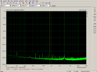
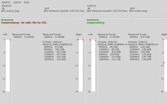
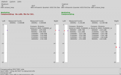
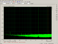
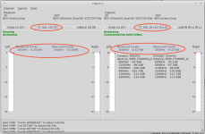
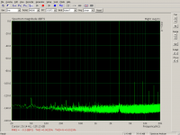
Examples of split-sides compensation at output (DAC) levels of -0.1dBFS and -1dBFS. Listed harmonics on each side (play/capture) show how much distortion the tool is reducing down to the levels shown on the Arta spectrums.
Examples of split-sides compensation at output (DAC) levels of -0.1dBFS and -1dBFS. Listed harmonics on each side (play/capture) show how much distortion the tool is reducing down to the levels shown on the Arta spectrums.
Attachments

30dB reduction, that's impressive! What sort of limit would this process have you think? For instance, suppose you have an opamp that distorts like -150dB, would that come out?
Jan
Jan
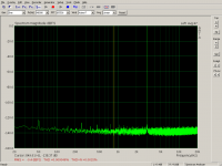
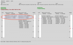
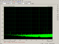
I chose output level close to 0dBFs intentionally so that both sides were forced to distort at max. Still the tool seems to compensate the overall distortion. For -3dB the compensated distortions are much lower - images attached.
Attachments
What sort of limit would this process have you think?
IMO the limit is HW stability of the soundcard and of course its noise floor.
For instance, suppose you have an opamp that distorts like -150dB, would that come out?
Well, I have not done any real measurements yet. But the distortion must be above the noise floor of the soundcard. The soundcard I use for development is quite noisy, does not go below -140dBFS. A very good device (RX6000) - I can imagine that. Since it is a regular soundcard, it should work with this tool. But for best results it must have output and input clocks linked to single master so that the exactly integer Hz frequencies can be generated, after the AD conversion. Non-integer frequencies will have their FFT smeared since I use FFT with binwidth exactly 1Hz.
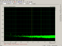
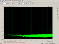
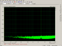
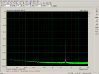
This is spectrum with artificially added distortion on DA side -130dB for second (6kHz) a fourth (12kHz) harmonics. The spectrum lines are clearly visible, correct level as measured by Arta cursor.
Attachments
What makes this even more interesting is that it can work with a nonlinear source. normally these ultra low distortion measurements require a "perfect" sine wave. However being able to extract added nonlinearities with a less than perfect source may tease out issues that are normally invisible.
Please update us on the required hardware and software platforms to make this work. I'll devote an extra computer to this. Its really interesting.
Please update us on the required hardware and software platforms to make this work. I'll devote an extra computer to this. Its really interesting.
Guys, thanks. Still lots of work ahead but it's slowly going forward.
🙂 😎
-RNM
Please update us on the required hardware and software platforms to make this work.
Linux: octave from distribution package, compiled playrec Playrec - What is Playrec? (simple since all build tools are directly available in any linux distribution), minor alsa configuration of alsa virtual loopback (snd-aloop available in any linux distribution), any measurement software using alsa (Arta in Wine, REW in java, jaaa, Visual Analyser in Wine etc.) - TESTED
Windows: octave windows installer, compiled playrec for the required sound API (ASIO, DirectSound, etc.), some virtual audio loopback (VB-cable VB-Audio Virtual Apps ?), any measurement software - NOT TESTED YET
OSX: the same - NOT TESTED
Hardware: Quad-core CPU - compensation running on both sides takes about 2 cores with safe margin to avoid underruns, with the quite inefficient octave GUI taking the largest toll :-( . Any recent ntb will do. RAM is not an issue.
Any duplex 2ch output + 2ch input soundcard with same clock for DAC/ADC (i.e. all regular soundcards). Of course the better the better, as always.
I'll devote an extra computer to this.
Linux machine would be more useful for the start, much easier to configure and troubleshoot. Plus it will take a while before I get to testing in windows. Thanks.
Last edited:
Is there a particular distribution to start with? SSD's are cheap enough that I may just build it from scratch.
Any recent will do. I have been using Mint Mate on all desktops I service for the last 5 years. No GUI glitter, low overhead, ubuntu PPA repos available if needed. Installation on SSD takes 20 minutes total.
For this project only distribution packages are required, no extras.
For this project only distribution packages are required, no extras.
Implemented initial support for output/input configurations
* dual/unbalanced
* balanced
* single channel
Playback/capture configurations are indepentently chosen directly on the main panel.
Balanced mode has calibrated levels for proper balancing (for now manually copied from fundamental levels in calibration files for each channel). On the panel screenshot the different levels on playback side are due to level calibration, capture side measures equal incoming levels.
All compensations are joint-sides performed on capture side.
Spectrums of stereo loopback:
A) DUAL -> DUAL (unbalanced), no compensation
B) BAL -> BAL, no compensation
C) BAL -> BAL + compensation
I compared two options:
1) subtracting before the compensation
2) compensating both channels before subtracting
The second option yielded half THD of the first one, therefore chosen for final implementation. On the panel you can see both channels compensating, each with different harmonic levels.
Attachments
CMRR measurement of the balanced input mode at the same 3kHz/-0.3dB. Just flip the playback mode from BAL to DUAL. Both input channels keep compensating, receiving same signals, without phase inversion. Arta measures RMS of the output -90dB.
Attachments

One part I've not understood yet in this is how you separate the non-linearities of the output and the non-linearities of the inputs. It's clear how you can take both together and effectively cancel them out.
When you separate output and input and put a 3rd non-linear piece in the middle, with gain, it seems everything must go out the window because you cannot anticipate how the various non-linear black boxes will interact with each other.
Have you explained this part before? Apologies in advance if I have missed it.
Typically the distortion is much lower at around -15 dBFS. You lose dynamic range but a high res fft (256K or higher) will still show all manner of harmonics. Have you tried that?
I set up Linux Mint Mate on a fresh ssd and will go through the other steps soon. They all look a little harder. Also Linux support for the Lynx card sucks. It's buried in a non Foss licensed package-OSS that's $15. I hope it can work and won't screw everything else up.
I set up Linux Mint Mate on a fresh ssd and will go through the other steps soon. They all look a little harder. Also Linux support for the Lynx card sucks. It's buried in a non Foss licensed package-OSS that's $15. I hope it can work and won't screw everything else up.

Demian - you picked perhaps the only soundcard without linux support 🙂. Please use a different one, lynx is a no-go in linux, unfortunately.
One part I've not understood yet in this is how you separate the non-linearities of the output and the non-linearities of the inputs. It's clear how you can take both together and effectively cancel them out.
Right, joint-sides compensation is nothing complicated. Even though I have not seen it used in any setup yet. But maybe I have just looked at wrong places 🙂
For splitting the distortion contributions - https://www.diyaudio.com/forums/equ...ensation-measurement-setup-7.html#post5645750
When you separate output and input and put a 3rd non-linear piece in the middle, with gain, it seems everything must go out the window because you cannot anticipate how the various non-linear black boxes will interact with each other.
First start the DUT chain without compensation, just passing. This will provide you with input levels for calibration. Calibrate the inputs at these levels with a calibration adapter and start compensation.
Output levels through the DAC are basically fixed, it can be attenuated with minimum distortion with resistor voltage divider at the output, no need to calibrate at various levels during measurement.
Cleaning DAC side is important because the DUT will rotate harmonics (non-flat phase response). Therefore no harmonics from the DAC should enter the DUT. DUT will create its own harmonics - those we want to measure.
I have yet to measure a real device. I hope a week should do.
Right, joint-sides compensation is nothing complicated. Even though I have not seen it used in any setup yet. But maybe I have just looked at wrong places 🙂
Well that's why I asked, right? Linearizing a pair of non-linear systems for a single point of operation is fairly trivial and routinely done. But looking at the link, yes, you have bit off a much larger piece with applicability far beyond audio, that's for sure.
Thanks for the link
That system also has an RME 9632 and an EMU 1616m and I have others. I'll wait on the Lynx exploration.
If I start with an external distortion free source and correct the ADC then the ADC can be used to calibrate a DAC?
Of course when distortion products match there is an add/subtract potential for them. That can create cancellation that is not real. Maybe that can be used to identify distortion removal vs system cancellation through selective phase switching?
That system also has an RME 9632 and an EMU 1616m and I have others.
I knew you would have many 🙂 For start please use a stereo soundcard if possible (ESI Juli, Xonar Essence ST(X) etc.). I quickly tested 8ch Xonar DX a few months ago and playrec had some problems - will look at it later.
For a soundcard with driver offering only multichannel device we would configure a stereo device in .asoundrc to use, so that playrec can see two channels only, for now.
I'll wait on the Lynx exploration.
You know a lot of people - should you happen to talk to someone from Lynx - it is a shame and sad they never released any documentation to allow creating linux driver. Some companies provide docs under NDA directly to driver developers. Although what level of know-how can be had in the communication protocol with a dumb device like sound card. This secrecy just makes no sense and affects their paying customers.
If I start with an external distortion free source and correct the ADC then the ADC can be used to calibrate a DAC?
I have not tested an external device. But theory says it is not optimal. The FFT uses limited number of bins (1Hz binwidth in my current version) and cannot measure fundamentals/distortions precisely for non-integer frequency.
On decent CPU (fast cores) the whole loop (incl. FFT in the analysis module) can run every 50ms, always providing updated phase measurement. But if you add 2,000Hz correction to 2,000.1Hz distortion, even in 50ms that will create a measurable error. When compensating harmonic from -100dB down to -140dB, every error/suboptimality stands out.
If DAC and ADC run from the same clock, the frequencies on both sides always fit exactly, for unlimited runtime.
Of course when distortion products match there is an add/subtract potential for them. That can create cancellation that is not real.
OK, let's suppose the DAC distortion cancels out with the ADC distortion in direct connection. The calibration will not yield any harmonic.
But if you run the same DAC distortion through the LP filter, it will be rotated differently than the fundament (different frequency) and will not cancel out with the ADC side anymore. The ADC distortion is created by the passing fundament and will be rotated differently than the DAC distortion. That is how the LP filter is used in splitting the contributions.
A simple test shows the effect:
Compensate joint-sides (regular phase subtraction) at voltage divider - clean spectrum.
Switch the path from voltage divider to LP filter producing the same fundament level (i.e. ADC will operate at the same distortion profile) and distortions appear - not compensated properly anymore.
Whereas the properly split compensation produces no distortions in the spectrum (up to HW limits) no matter which path is selected. Flipping the switch makes no change. The only conclusion I see is there are no DAC distortions to rotate.
Of course I have no other equipment to measure the DAC output precisely. But I have learnt a regular 24bit soundcard makes for a very sensitive device in this respect.
Maybe that can be used to identify distortion removal vs system cancellation through selective phase switching?
I do not understand, please can you elaborate more?
Last edited:
- Home
- Design & Build
- Equipment & Tools
- Digital Distortion Compensation for Measurement Setup