You should use a larger FFT window if you want to see the distortion buried by the noise.
Or use DiAna:
DiAna, a software Distortion Analyzer
You can vary the record settings to check if the harmonics detected are steady harmonics or if they are unpredictable. Chaotic unpredictable harmonics would be the end result of a good distortion correction.
Excellent results!
I have a question. Do you need some warming up time before calculating the coefficients? If so, which one is more sensitive to temperature drift, DAC or ADC? In my experience, DAC needs much time than ADC until it can recover a previous condition(120dB THD). DAC takes about 10 minutes, while ADC is 1 minute or less to reach stable operation. My DAC(AD9717) is probably resister ladder. Internal DAC in ADC(AD7960 SAR) is capacitor one. I don't know whether capacitor divider is more stable than resistor one or not. I guess DSM DACs and ADCs may have another performance.
I have a question. Do you need some warming up time before calculating the coefficients? If so, which one is more sensitive to temperature drift, DAC or ADC? In my experience, DAC needs much time than ADC until it can recover a previous condition(120dB THD). DAC takes about 10 minutes, while ADC is 1 minute or less to reach stable operation. My DAC(AD9717) is probably resister ladder. Internal DAC in ADC(AD7960 SAR) is capacitor one. I don't know whether capacitor divider is more stable than resistor one or not. I guess DSM DACs and ADCs may have another performance.
xx3stksm: Since developing the code always takes a while, the card is already well warmed up before testing 🙂 I am afraid I cannot answer your question, I am still focusing on fundamental issues.
But the code stores distortion parameters to individual files, separately for each side. It would be trivial to compare the measured/calculated distortion harmonic amplitudes at arbitrary calibration runs and analyse how they change with time/temperature, or compare various soundcards/technologies from this POW. Writing such analysis in octave will be simple.
But the code stores distortion parameters to individual files, separately for each side. It would be trivial to compare the measured/calculated distortion harmonic amplitudes at arbitrary calibration runs and analyse how they change with time/temperature, or compare various soundcards/technologies from this POW. Writing such analysis in octave will be simple.
Thank you for your reply. 🙂 If you recall the parameter you used at post #58 just after powering up DAC and ADC, can you have the same result as #58 or slightly another one?
When I get home today I will try yesterday params, without recalibration. But in real use the recalibration will be needed, soundcards do change their params. The final version should have an automated pass-through calibration tool with signal relays controlled by inexpensive USB arduino and Arduino package - Octave.
Thank you for your cooperation. My current DAC can calibrate relative accuracy up to almost 120dB THD. However, if the same coefficients are loaded next day, It can't have the same values after adequate warming up time. I don't know it comes from DAC or ADC. I would say it's almost impossible for a DIYer to guarantee 120dB THD though I sometimes have better THD than the value just after calibration. I highly appreciate your approach because there are very few real projects which have a successful result. SIM may exist but it's not real.🙂
I've read your project thread. Honestly, I do not understand all the details, not really able to help you with that.
I have already posted the planned use case of this compensation shim:
1) I am measuring without calibration (in pass mode).
2) A need to raise the resolution (= to eliminate hardware distortion) appears. I push a button (GUI or hardware), the automated tool runs through the calibration sequence at current output frequency (frequencies if dual-tone), current precise DAC level, current approximate ADC level (a relay-controlled resistor divider will have some step - 1dB? - to be determined).
3) After a few secs of calibration I continue with calibrated measurement. The calibration will last for a few minutes or longer (I have kept compensation running for an hour and the spectrum was still clean) - depending on the hardware used.
The tool works with any regular soundcard, no custom non-soundcard devices such as Q401 etc.
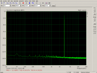
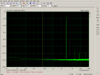
Cold boot, compensation only, calibration profiles from yesterday:
1) voltage divider
2) low-pass filter
3) pass mode - no compensation.
I would say the hardware is rather consistent.
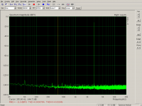
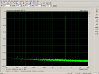
Recalibrated, increased FFT in Arta:
4) voltage divider
5) LP filter
I guess the limit of the technology is reached. Cleaner spectrum will need virtual balanced inputs, on the todo list...
1) voltage divider
2) low-pass filter
3) pass mode - no compensation.
I would say the hardware is rather consistent.
Recalibrated, increased FFT in Arta:
4) voltage divider
5) LP filter
I guess the limit of the technology is reached. Cleaner spectrum will need virtual balanced inputs, on the todo list...
Attachments

Last edited:
Thank you very much for your measurement. It's surprising for me to know cold start with yesterday parameter still has good performance. The difference between previous parameters and recalibrated one is almost 6dB(0.00018% and 0.000079%). My setup has to wait at least 10minute to recover yesterday's performance, where the dominating factor is DAC. But after 10 minutes, the difference may be 3dB. I guess this is because of DAC architecture. Mine is R2R.🙁
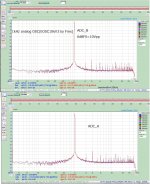
Anyway, I need an example to have a full understanding of your system. I still can't understand the detail of your project. What I 'm sure is that you have reliable data and are on the way to be successful. The attached is FFT of the analog OSC(by Frex) by my DIYed SAR ADC(AD7960). I have two ADC boards. Both are the same hardware with two channels. So, the pic has four outputs. However, they don't have the same outputs. It's not surprising but reasonable for me. It's very difficult to have absolute accuracy in more than 110dB THD.
If I want to apply your software on this setup, what do I need? ADC outputs 24bit/96kHz TOSLINK to Windows7pro 64bit PC. FFT is Audio Tester. If I'm not wrong, you can do a calibration on both sides, i.e. OSC and ADC. Is it possible to calibrate only ADC and OSC intact? I still can't understand why independent calibration is possible. Please correct me if I have misunderstood.
Attachments
Cold-boot performance with calibration profile from the day before depends solely on hardware. The soundcard I happen to test on (Infrasonic Quartet) seems rather consistent. I was also surprised by how little the params changed from the day before. A different card will have a different temperature/long-term stability.
The principle I use is quite simple (well, there were quite a few trials before 🙂 ).
Basic Principle
-----------------
The tool is a shim between the real soundcard and a virtual loopback soundcard. The actual measurement software (e.g. Arta) communicates with the loopback soundcard.
PASS: read samples from capture soundcard, copy to playback soundcard.
CALIBRATION: Measure FFT, determine complex amplitude (amplitude & phase) of fundamental freqs (one or two, more are not supported), based on the fundamentals determine complex amplitude of harmonics (plus of by-products for dual tone), store the values to calib file. FFT is samplerate-samples long (1 second of data), i.e. only whole Hz values are supported.
COMPENSATION: Measure incoming fundamentals with FFT, select corresponding calibration file, determine current fundamental phase offset, generate distortion harmonics at correct but inverted phase, add (i.e. subtract) to the incoming stream, write the result to the playback soundcard. Measuring fundamental phase and generating new distortion harmonics occurs every cycle (currently 200ms), in case of underrrun on the incoming stream.
GENERATION: Drop incoming samples, generate sine signal as requested and write new samples to the playback soundcard.
Every cycle samples (either original or modified) are passed to the playback soundcard, making sure the measurement software gets some data and does not get stuck.
The octave script runs in two instances/configurations on both sides. The calibration mode makes sense only on the ADC side, while generation mode only on the DAC side. Both sides can pass and compensate.
Determining DAC and ADC distortions - splitting the whole-loop values
---------------------------------------------------------------------------------
Obviously the parameters measured by calibration represent distortions of the whole loop - DAC side combined with the ADC side. There is no way to measure a contribution of only one side contribution - we do not know how much each side contributes to the measured overall distortion at each harmonic frequency. If it cannot be directly measured, could it be calculated somehow? Octave is a great math software with almost endless capabilities, let's use it!
We need a way to split the overall distortion Dtotal into DAC Ddac and ADC Dadc components. (Each distortion has amplitude and phase (complex number))
Obviously for each harmonic frequency:
We know Dtotal (measured). Unfortunately this equation has infinite number of solutions. Clearly we need more equations.
I tried countless scenarios with voltage dividers, various compensations on each side, but always ended up with mutually dependent equations (their matrix determinant was always zero).
Clearly more information is needed to the mix. We need to "kick" the harmonics in a precisely controlled manner and measure what happens. This could generate another equation yielding more information.
The most typical circuit rotating phase with frequency is a low-pass filter. Its behaviour at respective harmonic frequencies can be very precisely measured with our setup. Another mode MEASURE_TRANSFER was added to the octave script, measuring/storing attenuation and phase shift at incoming frequency (both channels are used, one receives direct sine, the other the attenuated and phase-shifted signal from the filter).
After measuring overall distortions for same signal passing the filter, we get second equation. Writing this equation properly took me a while but the split-compensation results suggest it reflects reality correctly.
Only Ddac distortions go through the filter. Dadc distortions originate from the fundamental going through the filter.
Two equations, their right values are known, octave offers great curve-fitting/solving tools. Complex numbers could have been used, but I chose to generate/curve-fit sine functions as they are more descriptive and much easier to troubleshoot by plotting the measured and estimated sine curves.
Generating known values for Eq1 (direct through voltage divider) - nonlinear-compensation/run_splitting.m at master * pavhofman/nonlinear-compensation * GitHub
Generating known values for Eq2 (LP filter of the same attenuation at fundamental freq) -
nonlinear-compensation/run_splitting.m at master * pavhofman/nonlinear-compensation * GitHub
Eq1: nonlinear-compensation/lpEqs.m at master * pavhofman/nonlinear-compensation * GitHub
Eq2: nonlinear-compensation/lpEqs.m at master * pavhofman/nonlinear-compensation * GitHub
Finding the four parameters (amplitude and phase of ADC and DAC distortions at one harmonic freq) by curve-fitting the two equations to the two measured and pre-generated sine references: nonlinear-compensation/run_splitting.m at master * pavhofman/nonlinear-compensation * GitHub
When found to work, it is simple now 🙂
The principle I use is quite simple (well, there were quite a few trials before 🙂 ).
Basic Principle
-----------------
The tool is a shim between the real soundcard and a virtual loopback soundcard. The actual measurement software (e.g. Arta) communicates with the loopback soundcard.
PASS: read samples from capture soundcard, copy to playback soundcard.
CALIBRATION: Measure FFT, determine complex amplitude (amplitude & phase) of fundamental freqs (one or two, more are not supported), based on the fundamentals determine complex amplitude of harmonics (plus of by-products for dual tone), store the values to calib file. FFT is samplerate-samples long (1 second of data), i.e. only whole Hz values are supported.
COMPENSATION: Measure incoming fundamentals with FFT, select corresponding calibration file, determine current fundamental phase offset, generate distortion harmonics at correct but inverted phase, add (i.e. subtract) to the incoming stream, write the result to the playback soundcard. Measuring fundamental phase and generating new distortion harmonics occurs every cycle (currently 200ms), in case of underrrun on the incoming stream.
GENERATION: Drop incoming samples, generate sine signal as requested and write new samples to the playback soundcard.
Every cycle samples (either original or modified) are passed to the playback soundcard, making sure the measurement software gets some data and does not get stuck.
The octave script runs in two instances/configurations on both sides. The calibration mode makes sense only on the ADC side, while generation mode only on the DAC side. Both sides can pass and compensate.
Determining DAC and ADC distortions - splitting the whole-loop values
---------------------------------------------------------------------------------
Obviously the parameters measured by calibration represent distortions of the whole loop - DAC side combined with the ADC side. There is no way to measure a contribution of only one side contribution - we do not know how much each side contributes to the measured overall distortion at each harmonic frequency. If it cannot be directly measured, could it be calculated somehow? Octave is a great math software with almost endless capabilities, let's use it!
We need a way to split the overall distortion Dtotal into DAC Ddac and ADC Dadc components. (Each distortion has amplitude and phase (complex number))
Obviously for each harmonic frequency:
Code:
Ddac + Dadc = DtotalWe know Dtotal (measured). Unfortunately this equation has infinite number of solutions. Clearly we need more equations.
I tried countless scenarios with voltage dividers, various compensations on each side, but always ended up with mutually dependent equations (their matrix determinant was always zero).
Clearly more information is needed to the mix. We need to "kick" the harmonics in a precisely controlled manner and measure what happens. This could generate another equation yielding more information.
The most typical circuit rotating phase with frequency is a low-pass filter. Its behaviour at respective harmonic frequencies can be very precisely measured with our setup. Another mode MEASURE_TRANSFER was added to the octave script, measuring/storing attenuation and phase shift at incoming frequency (both channels are used, one receives direct sine, the other the attenuated and phase-shifted signal from the filter).
After measuring overall distortions for same signal passing the filter, we get second equation. Writing this equation properly took me a while but the split-compensation results suggest it reflects reality correctly.
Only Ddac distortions go through the filter. Dadc distortions originate from the fundamental going through the filter.
Code:
Ddac_attenuated_and_phase_shifted + Dadc_from_fundamental_attenuated_and_phase_shifted = Dtotal_through_filterTwo equations, their right values are known, octave offers great curve-fitting/solving tools. Complex numbers could have been used, but I chose to generate/curve-fit sine functions as they are more descriptive and much easier to troubleshoot by plotting the measured and estimated sine curves.
Generating known values for Eq1 (direct through voltage divider) - nonlinear-compensation/run_splitting.m at master * pavhofman/nonlinear-compensation * GitHub
Generating known values for Eq2 (LP filter of the same attenuation at fundamental freq) -
nonlinear-compensation/run_splitting.m at master * pavhofman/nonlinear-compensation * GitHub
Eq1: nonlinear-compensation/lpEqs.m at master * pavhofman/nonlinear-compensation * GitHub
Eq2: nonlinear-compensation/lpEqs.m at master * pavhofman/nonlinear-compensation * GitHub
Finding the four parameters (amplitude and phase of ADC and DAC distortions at one harmonic freq) by curve-fitting the two equations to the two measured and pre-generated sine references: nonlinear-compensation/run_splitting.m at master * pavhofman/nonlinear-compensation * GitHub
When found to work, it is simple now 🙂
Last edited:
Thank you for the elaboration. I have understood what you mean and why split-compensating can be realized! I couldn't imagine the true meaning of voltage divider and LPF. I respect the inventor who used them as a discriminator. The scales fell from my eyes. We use the phrase exactly as it is in Japanese because the original was translated from English.😀
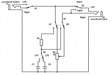
Calibration sequence plan for frequency F, current output level Ao, input level Ai
1) Measuring LP Filter Transfer
----------------------------------
This step does not require any preliminary calibration as it uses only relative values between channels.
* Switch S1 at right output channel
* S2 (left input) at direct
The step involves three substeps:
A) Measuring/remembering attenuation and phase shift at harmonic frequencies of fundamental F, using left/right ADC channels
* S3 at LP
* S4 at corresponding capacitor as needed
Measured using sine fitting, a few seconds for 10 harmonics of 1kHz fundamental
B) Measuring phase shift between ADC channels for at harmonic frequencies of fundamental F, using left/right ADC channels
* S3 at VD
Measured using sine fitting, a few seconds for 10 harmonics of 1kHz fundamental
C) Subtracting the interchannel phase shift from the filter phase shift measured in A, storing transfer to file.
This rather lengthy calibration step should not be required often as it measures only two passive components, calibration should hold.
2) Measuring Gain of Each Output Channel for Calibrating Virtual Balanced Output
* S2 (left input) at direct
* S1 at right output channel - measure left ADC channel amplitude
* S1 at left output channel - measure left ADC channel amplitude
Since both DAC channels are measured with one ADC channel, DAC gain coeffs can be directly calculated for each DAC channel. The DAC gain correction makes sure both channels output exactly same levels, allowing for correctly balanced output.
This step requires capturing only a few amplitudes of fundamental to measure the amplitude, should take a fraction of second.
3) Measuring/Calculating Split Distortions of both ADC and DAC channels
* S1 at right output channel
* S2 at =right - both input channels will receive same signal
Plan - fitting Rout -> Lin & Rin at the same time
Step A) Measuring fund/distortion peaks for voltage divider equations
* S3 at VD at fundamental F
* Potentiometer at level corresponding to filter attenuation at fundamental F
* regular calibration sequence resulting in joint-sides params on both channels - approx 1 second
* since both input channels are fed from single output channel, the measured fundamental amplitudes provide directly interchannel gain difference for gain correction of virtual balanced inputs.of fully compensated
Step B) Measuring fund/distortion peaks for filter equations
* S3 at LP at fundamental F
* regular calibration sequence resulting in joint-sides params - approx 1 second
Step C) Calculating split calibration values for Rout, Lout, Rout
* 4 equations with 6 fitted parameters (3 x ampl&phase), no delay
Step D) Measuring fund/distortion peaks of Lout with ADC channels split-compensated
* S1 at left output channel
* S3 at VD
* regular calibration sequence at any of the output channels. Since both ADC channels are already compensated at this step (for the incoming input level), the measured distortions correspond to yet uncompensated DAC left channel. Takes approx 1 second.
Summary
The relatively long step 1 measuring filter transfer should not be performed often.
The standard calibration steps 2, 3, 4 measure only at fundamental freq and should not take more than a few secs when fully automated (relays, relay-switched R-2R network). They result in:
* split calibration of all output and input channels at current frequency, current output level and closest current input level
* equal-level calibration for virtual balanced outputs and virtual balanced inputs
The balancing of outputs/inputs (when enabled in GUI) will be performed by inverting (DAC side)/subtracting(ADC side) split-compensated and equal-leveled single channels. This should yield maximum performance from the available hardware.
Time to rewire the existing tool and start coding the steps...
Attachments
Last edited:
Does your compensation algorism handle four harmonics(2nd,3rd,4th, and 5th order)? What I mean is DSM ADC and SAR ADC apparently have a different pattern of distortion. AFAIK, distortion of DSM ADC is usually up to 5th order. That's why you have a successful result with compensation up to 5th order.
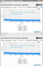
Distortion of SAR ADC has wide deviation than DSM ADC(my post #69). The evaluation board by AD also has such performance (attached pic). This is probably because of its architecture, where internal C2C DAC may be the dominating distortion source. Analog components, irrelevant to R2R or C2C, can't be ideal like DSM ADC which has no analog ones in a conversion process. The reason I use SAR is that they have better SNR than DSM though they are inferior in THD.
Anyway, I have a plan to design DSM ADC(AD7768) which probably doesn't have high order harmonics more than 6th.
Attachments
The harmonics-detection code (by miero) covers all harmonics up to fs/2. The dual-tone code looks for all the by-product combinations too. At dual-tone 4k+4.5k example of https://www.diyaudio.com/forums/equ...ensation-measurement-setup-5.html#post5622372 the code compensates tens of harmonic/by-products distortions simultaneously.
The splitting code is still hard-coded for 3kHz and 5 harmonics. TBD, as almost everything 🙂
The calibration and compensation code can work with any frequency of distortion (whole Hz). However, there must be a way to determine correct phase when generating the distortion compensation sine. Distortions related to the fundamentals (both single and dual tones) have their current phase calculated by determining the time offset between stored calibration profile and current time from the fundamental params. That is not possible for unrelated distortions, e.g. 50Hz mains, 1kHz USB frames, soundcard oscillator by-products, etc. We can measure them, generate the compensating sine, but do not know what phase to use which renders it useless.
However, there must be a way to determine correct phase when generating the distortion compensation sine.
I thought your algorism uses 5th order polynomial to compensate distortion. But If you generate the distortion compensation sine with the opposite phase, It doesn't mean polynomial calculation but sum between the input signal and the opposite phase sine. If so, it seems to me that all harmonics can be treated(multiples of 1Hz) and have a promising future. Am I correct?
Well, my previous post started with "the harmonics detection code covers all harmonics up to fs/2" 🙂
The polynomials are long gone, they were a good start but proved incapable of inverting all distortions to opposite phase. The hard-force (measure -> generate opposite) is reliable and works for (limited) two-tone signal too (splitting does not support two tones, hopefully not yet).
The polynomials are long gone, they were a good start but proved incapable of inverting all distortions to opposite phase. The hard-force (measure -> generate opposite) is reliable and works for (limited) two-tone signal too (splitting does not support two tones, hopefully not yet).
great!
I'm very happy to know your successful results was done by the hard-force. Honestly speaking, I'm doubtful about the polynomial solution because it's too complicated and can't handle large numbers of harmonics. Generating opposite phase sines(the hard-force) is simple and effective. It's a mystery why nobody(including me) designed such compensation algorism so far both in software and hardware.
The scales fell from my eyes again. I can't find a negative issue about the hard-force besides some limitations(amplitude and frequency) which are usually not fatal for a DIYer though it's not preferable for a commercial product. My current DIYed ADC isn't ideal because the same two ADCs can't output the same results with the same input signal. I can say they are ideal up to 110dB THD. If I implement such compensation algorism into my ADC, I'm sure I can guarantee up to 130dB THD. I have decided to design the firmware of FPGA to do the hard-force next spring. It can achieve a successful result like you in hardware configuration.
I would not want to program all the math in FPGA, but if you are skilled in that, it is certainly doable. The calibration profile holds surprisingly stable, you may even not need calibration often. Unfortunately dependence on signal level is strong, the calibration must involve multiple levels.

- Home
- Design & Build
- Equipment & Tools
- Digital Distortion Compensation for Measurement Setup